Abstract
There was not only one steel primer used on WTC tower structural steels, but at least one other primer:
LaClede Standard Primer is a zinc-free paint formulation with which the floor joists of the twin towers were painted.
The painted area of these LaClede-painted floor joists in both towers was roughly 600,000 m2 while Tnemec is only known to have been specified for about 400,000 m2 of perimeter column surface. For the rest of the structural steel – core columns, hat truss and others, a total of 300,000 m2 the primer used isn't known.
Claims that Niels Harrit proved that some red-gray chips in the WTC dust are not WTC primer are basing this claim on the FALSE assumption that Tnemec was the only primer used. In fact, I will show that the chips that Harrit proved to not be Tnemec look very much like LaClede Standard Primer.
Introduction
Back in May 2009, Niels Harrit wrote “Why The Red/Gray Chips Are Not Primer Paint” [1]. In it, he shows the composition of Tnemec Red, which has, among others, Zinc Yellow as it's main pigment. He then shows, in his Fig. 5, the XEDS spectra of the red layers of four red-gray chips labeled (a)-(d) from WTC dust, which he and 8 others had characterized in a paper published in April 2009 [2]. Result: Since Chips (a)-(d) contain no Zn, they can't be Tnemec. I agree with this finding – these four chips indeed are not Tnemec.
But Tnemec wasn't the only steel primer used in the WTC! As far as is known, Tnemec was the specified primer for the WTC perimeter columns[3].
At least one other primer has been applied to WTC steel: LaClede Steel Company, manufacturer of the floor trusses [4], used their own shop primer, or LaClede Standard Primer with the following composition [5]:
Pigment: 28.5% by weight
Iron Oxide: 55%
Aluminium Silicate: 41%
Strontium Chromate: 4%
Vehicle: 71.5%
Epoxy Amine and other: 100%
I find this false claim, that there was only one primer (Tnemec) used in the WTC towers, quite often in recent articles by people who want to defend Harrit e.al.'s claim that the red-gray chips are somehow nano-thermitic, for example at AE911T [6a]. These authors need to understand that they err: They have so far overlooked LaClede Standard Primer!
LaClede Standard Primer
The above formulation of LaClede Standard Primer can be broken into chemical elements, with a few reasonable assumptions:
“Iron oxide” is hematite, chemical formula Fe2O3, a red pigment. Hematite pigments are bright red at particle sizes between 100 and 300 nanometers, and in that size it is universally used in all kinds of paints.
“Aluminium Silicate” is kaolin, chemical formula Al2Si2O5(OH)4, a clay mineral very commonly used in paints to control gloss consistence. Kaolin appears naturally in platetelets some micrometers across and some tens of nanometers thick, which tend to stack.
The cured epoxy vehicle is polymeric and it is difficult to give a sum chemical sum formula, but it is dominated by carbon (C, 68% by weight), oxygen (O, 13%), hydrogen (H, 9%) and nitrogen (9%)
With these chemical formulas, I computed the elemental composition of LaClede Standard Primer:
C: 48% by weight
O: 21%
Fe: 11%
H, N: 7% each
Si: 2.5%
Al: 2.4%
Sr: 0.5%
Cr: 0.3%
Using DTSA-II, a free multiplatform software package for quantitative x-ray microanalysis [7], I simulated a bulk sphere with the above chemical composition, using the same 20 keV that Harrit e.al. used:
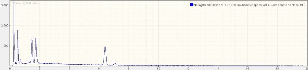
The five larges peaks are, from left to right: C, O, Al, Si and Fe. Note the relative height: C is nearly twice as high as O; O is higher than than Al and Si; Al and Si are nearly equal; Fe is perhaps 70% of Si. Note that there is a small bump for Cr (chromium) at 5.4 (keV) on the x-axis, but none for Sr (strontium). The reason why strontium is invisible is that its main peak would be nearly exactly where the Si peak is, so it is hidden under the much larger Si signal.
We have estimated that the total painted surface area of the LaClede floor joists was about 600,000 m2 in both towers combined, or 50% more than the surface area of the exterior columns that were painted with Tnemec.
Discussion
Compare the XEDS graph of LaClede primer with Harrit's chips (a)-(d):
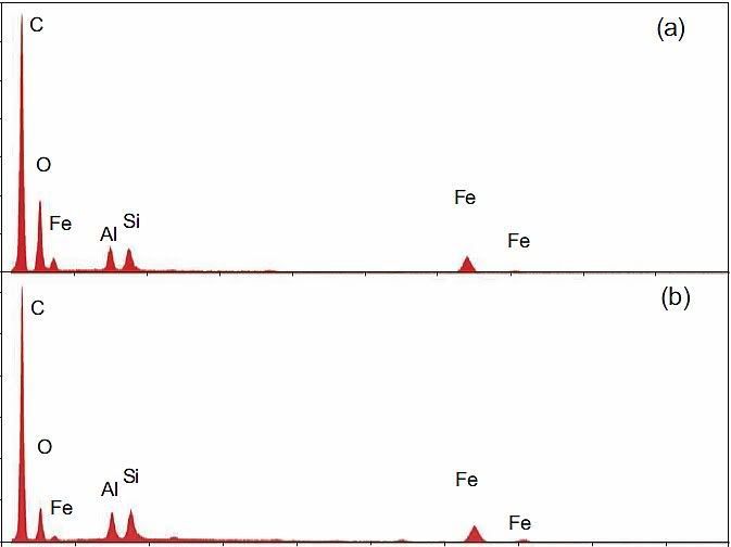
Now notice: C is again the highest peak by far, O is second in three of the four chips. Al and Si are nearly the same, Fe is typically about 70% of Si. And there is a small bump at 5.4 keV in chips b and d, which is chromium!
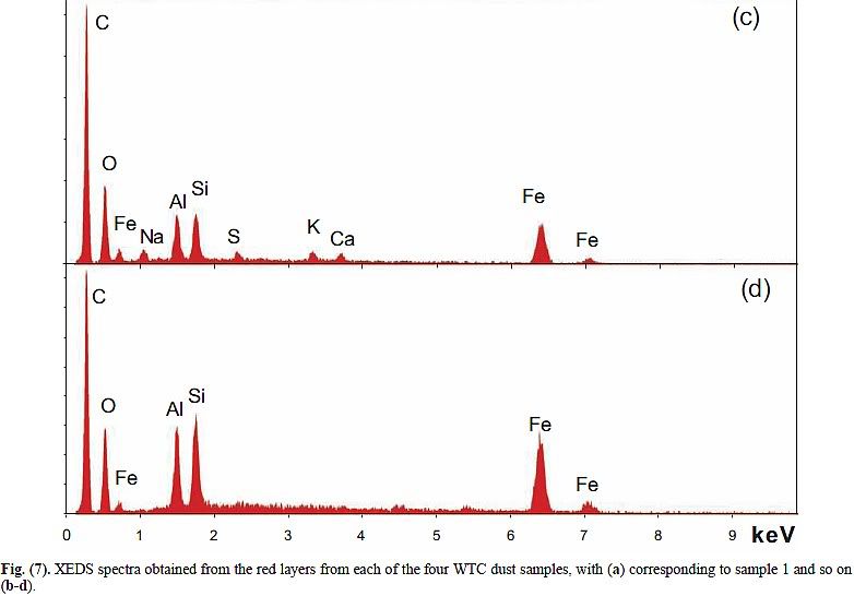
In [1], Harrit presents a more detailed XEDS graph for chip (a):
Do you see how Harrit has detected Cr (chromium) and even Sr (strontium) in trace amounts? Yep, there are also signals for S and Ca. Perhaps a tiny inclusion of gypsum, but I wouldn't bet on that.
Conclusion
I have shown that Harrit's argument, re-gray chips (a)-(d) can't be primer because they are not consistent with Tnemec, falls flat on its face, because Tnemec was not the only primer used on WTC steel. Another primer that must be considered is LaClede Standard Primer, and there could be even other primers of which no documentation seems to exist (we don't know for example which primer, or primers, was painted on the core columns and beams).
I have further shown that the XEDS spectra of chips (a)-(d) are very much consistent with the the paint formulation of LaClede Standard Primer.
I call on all honest and science-minded people in the 9/11 Truth Movement to reject Harrit's claim that chips (a)-(d) can't be primer as premature and consider LaClede Standard primer as a possible source for some of the red-gray chips. Tnemec may be another such source of other chips; in fact it seems that the MEK-soaked chip in [2] is consistent with Tnemec, as I have shown in another post [8] – this MEK chip can't possibly be identical with chips (a)-(d)! [9].
I further call on all students of [2] to realize that Harrit e.al. have analysed several different kinds of red-gray chips, and not pretend they are all basically the same.
References
[1] Niels H. Harrit: Why The Red/Gray Chips Are Not Primer Paint. Open Letter, May 2009
[2] Niels H. Harrit, Jeffrey Farrer, Steven E. Jones, Kevin R. Ryan, Frank M. Legge, Daniel Farnsworth, Gregg Roberts, James R. Gourley and Bradley R. Larsen: Active Thermitic Material Discovered in Dust from the 9/11 World Trade Center Catastrophe. The Open Chemical Physics Journal, 2009, 2, 7-31
[3] Carino, N. J.; Starnes, M. A.; Gross, J. L.; Yang, J. C.; Kukuck, S. R.; Prasad, K. R.; Bukowski, R. W.: Passive Fire Protection. Federal Building and Fire Safety Investigation of the World Trade Center Disaster (NIST NCSTAR 1-6A). 2005. Page 87: “...Series 10 Tnemec Prime (99 red), which is the primer that was specified for the exterior columns”
[4] Luecke, W. E.; Siewert, T. A.; Gayle, F. W.: Contemporaneous Structural Steel Specifications. Federal Building and Fire Safety Investigation of the World Trade Center Disaster (NIST NCSTAR 1-3A). 2005. Table 3-5, p. 21
[5] Gross, J. L.; Hervey, F.; Izydorek, M.; Mammoser, J.; Treadway, J.; Fire Resistance Tests of the Floor Truss Systems. Federal Building and Fire Safety Investigation of the World Trade Center Disaster (NCSTAR 1-6B). 2005. Appendix B, p. 157 of the PDF
[6a] AE911Truth Staff: FAQ #7: Aren’t the Red-Gray Chips Identified in the WTC Dust Merely Primer Paint from the WTC Steel Structural Elements?. Architects & Engineers for 9/11 Truth, 2012/03/15. Retrieved 2012/03/16
[7] Chuck Fiori, Carol Swyt-Thomas, and Bob Myklebust: DTSA-II Desktop Spectrum Analyser. Retrieved 2012/03/15
[8] Oystein: Steven Jones proves primer paint, not thermite. 2011/03/31
[9] Oystein: Why red-gray chips aren't all the same. 2012/03/14
'Do you see how Harrit has detected Cr (chromium) and even Sr (strontium) in trace amounts? Yep, there are also signals for S and Ca. Perhaps a tiny inclusion of gypsum, but I wouldn't bet on that.'
ReplyDeleteCan you not tell the difference between contaminated chips and the ones that have been cleaned?
- the washed chips do not match any of the paints that you suggest. None of your paints are explosive either for that matter.
“Aluminium Silicate” is kaolin, chemical formula Al2Si2O5(OH)4,
But Harrit demonstrated that (1)the silicon is not chemically bound to the al, therefore it cannot be al silicate. - (2)is is also shown that there is elemental al present.
There is no point debating with people like you - I could just as well try to debate Creationists.
To Anonym:
ReplyDeleteSigh...
How many dioptries do you have? You really do not see ANY resemblance of XEDS spectra of Bentham chips (a) to (d) and simulated spectra of Laclede paint, depicted above? Unbelievable:o)
Where did you get some data that any of the Bentham chips was explosive???
Harrit demonstrated (not really convincigly) that only in so called MEK chip (soaked in MEK) silicon was not bound to aluminum Al, which is fully expected, since this chip was particle of Tnemec primer which contained several silicon and aluminum paint pigments; they can separate during soaking and they are naturally separated even before soaking.
MEK chip was apparently different paint (Tnemec paint) than chips (a) to (d) (Laclede paint), that is what this blog is about now.
Thanks, Anonymous, for your comment, and Ivan for the reply. I think you are spot on, Ivan. One more thing:
ReplyDelete"Can you not tell the difference between contaminated chips and the ones that have been cleaned?"
Harrit's XEDS graph with the strontium and chromium signals is from the fresh, newly-exposed clean surface of a chip they just cut in half. So that is a pretty uncontaminated surface, and Sr and Cr are likely in fact an ingredient of the red layer, not surface contamination. Sorry if that was not clear from my articel.
You still do not understand what you are talking about:
ReplyDelete1. Your own analysis of composition by weight of your primer paint and Basile´s samples debunks your work. The only match is amount of oxygen, thats it. All the others are WAY OFF, especially Iron. Basile´s chips cannot be this primer. Better luck next time.
2. Anyway, even if you find paint that LOOKS similar to Harrit chips, you have to ignite them to see if they are energetic. THIS IS WHAT HARRIT ET AL DID BECAUSE THE NANOTHERMITE DESIGNERS THEMSELVES DO THE SAME DSC TEST TO SEE IF THEY ARE ENERGETIC:
Gash et al 2004 (reference nr 21 in Harrit et al paper): To determine whether the material was energetic differential scanning calorimetry (DSC)was performed.
3. You have claimed that the DSC tests are meaningless, and the kids at JREF may believe you, but as is obvious from the above quote from Gash et al, anyone who has actually done the research will know better. You have debunked yourself with this kind of BS, and it is pathetic to say the least.
You are committing FRAUD if you do not stop lying about the dsc tests. It has already been said to you that it is hard to take you seriously.
4. 'Where did you get some data that any of the Bentham chips was explosive?'
Assuming you have read and UNDERSTOOD bulletins nr 2 and 3 above, you can continue reading research by Gash et al and see how they use the DSC tests to compare the width of the peaks to determine the EXPLOSIVE POWER. They show that the nanothermite peaks are MUCH NARROWER than conventional thermite. Same amount of energy density but released in a FRACTION of the time.
So you ask 'how do Harrit et al know that the chips are explosive', and the answer is: THE SAME WAY GASH ET AL KNOW THAT NANOTHERMITE IS EXPLOSIVE.
5. Given that you are CAPABLE of understanding all this, which I doubt, and still want to continue your Paint-Gospel, you may want to realize that the with of a thermite peak is many times over broader than a nanothermite peak...
and paint provides an ever wider peak.
- Farrer et al have already tested paint in a dsc, and the results are easy to understand
http://world911truth.org/interview-with-jeff-farrer-nanothermite-paper-scientist/
Paint does not provide a narrow explosive peak at all, and neither does it produce molten iron spheres.
IT IS AMAZING THAT NONE OF YOU JREF ´DEBUNKERS´HAVE MANAGED TO SHOW THAT YOUR PRIMER PAINT MATHCES THE DSC PEAKS AND PRODUCES MOLTEN IRON SPHERES...AFTER ALL YOU KIDS HAVE ONLY HAD 3 YEARS TO DO IT.
This comment has been removed by a blog administrator.
ReplyDeletehttp://the911forum.freeforums.org/post19857.html#p19857
ReplyDeletePlease enlighten us, waiting for answers...
Excuse me, I had not checked comments here or the911forum in a while. I don't have time today and tomorrow to read and reply there, but will do so later this weel.
DeleteAre you "Ziggi"? I am ok with anonymous comments, but of course prefer some sort of identification.
There better be more primer-paint possibilities because the chips from Harrit et al are clearly not laclede, for 2 simple reasons:
ReplyDelete1) None of main ingredients,al/fe/oxygen/si/C, match the primer, some are off by a huge margin, such as fe, as has been pointed out to you.
2) the more detailed XEDS graph of sample a should show strong signals for sr and cr, the peak heights for which should be about 1/5 to 1/6 of the al and s peaks. But the tiny 'peaks' in that graph are more like 1/500 to 1/600...there is hardly evidence of clear signals for sr and cr, and more importantly not at all in the required amounts.
- Judging by their recent silence, it seems that your buddies at JREF have discovered the same thing. Points 1 and 2 above do not suggest that the chips must be your primer paint, applying Occam´s razor. Also, no-one has pointed out a primer paint yet that survives paint solvents, produces molten spheres and outperforms TNT either...not helping out from the Occam-perspective. But yet there are still people that insist that it is not only possible that they are paint, but also the most likely scenario. This is starting to look really silly.
Maybe its time to get real? REALLY.
Bye the way, you really should acknowledge the existence of organic nanothermites and hybrids..as were pointed out from the very beginning as references in Harrit et al. Think about the reason WHY they included them.
You should also know that the very same references give you examples of nanothermite with al fuel coated with...kaolin clay-like material to prevent oxidation of the al fuel. This would look like kaolin plates but in fact be especially coated al, to get the most elemental al possible.
Hi,
Deletethis is a weird comment. It appears like you haven't read the article you are commenting, or perhaps you can't see the graphs I posted?
To reply to the points you raise:
1.) Compare the first to spectra in my post above: The first is what the LaClede paint would look like, the second shows Harrit's four chips (a)-(d). Compare them: You will find that both graphs resemble each other very closely, specifically the Fe-peaks reklative to the Al- and Si- peaks are precisely what is expected from LaClede paint.
Could you please tell me out where allegedly it has been pointed out by me that ingredients are off by huge margins, and by whom? Thanks.
2.) No, you are wrong about the expected peak heights for Sr and Cr. See my first graph, it contains all the Sr- and Cr-peaks you can expect from Laclede paint: Sr would be all but invisible to the eye, and Cr shows as a very small hump around 5.4 keV whise height is more like 1/8th-1/9th that of the Si-peaks - you actually see humps in Harrit's data that are between 1/16th and 1/10th of the Si-peaks. Yep, that's less than expected, but in the ballpark; the difference can easily come from the unknown geometry and size of the samples and the EDS device, from the precise properties of the matrix, etc. For example: For my simulation, I modelled the LaClede paint as spheres with a diameter of 25 micrometers. That choice is somewhat arbitrary. If I model it as bulk material, then suddenly the expected Cr-signal has only 1/16th the peak height of Si, and then there would be "too MUCH" Cr signal in Harrit's data. The truth may well be somewhere in the middle. Conclusion still: The simulation and Harrit's data (a)-(d) are an amazingly good match for ALL ingredient elements of LaClede paint.
Where and how can you see that the Si-signal is 500-600 times as high as the Si-peak?? The Cr-peak is about 41 pixels in Harrit's detailed graph, and he caps the peaks at 324 pixels - so you can know that Si is at least 8 times as high. No more can be inferred. In fact, if the Cr-peak were 1/500th of the Si peak, it would be 1 pixel! See how wrong you are? Amazing how you can't see that!
Some more points:
DeleteI think the recent "silence" at the JREF comes from the fact that everybody has long since understood that I am right and Harrit is wrong and there's really little more to be said about that.
"No-one has pointed out a primer paint yet that survives paint solvents" - so what?
"(No-one has pointed out a primer paint yet that) produces molten spheres" - I understand this being looked into by Dr Millette at this time
"(No-one has pointed out a primer paint yet that) outperforms TNT" - WRONG. I have pointed out often that nearly EVERY organics-based primer paint can be expected to outperform TNT in terms of energy. Your earwax and your dried ejaculate also outperform TNT in that department, did you know that? It is entirely unremarkable for organics-based stuffs to outperform TNT! Why can't truther understand this simple point that TNT and thermite do NOT contain a remarkable amount of energy at all?
"Bye the way, you really should acknowledge the existence of organic nanothermites and hybrids" - why? I acknowledge that, and I acknowledge the existence of earwax and dried ejaculate. What has that got to do with the case at hand? Nothing! You are begging the question!
"Think about the reason WHY they included them" - to sell lies to gullible truthers.
"You should also know that the very same references give you examples of nanothermite with al fuel coated with...kaolin clay-like material to prevent oxidation of the al fuel." - Can you be more specific, please?
"This would look like kaolin plates but in fact be especially coated al, to get the most elemental al possible." No - a sphere maximises volume / minimizes inert (coated) surface. You are very obviously wrong.
Now what's your source that anyone has created plate-like Al-nanoparticles and coated them with anything? Please be specific (citation)!
"Think about the reason WHY they included them" - to sell lies to gullible truthers.
ReplyDeleteAre you retarded? Harrit et al point to research by the nanothermnite pioneers that includes organic nanothermites....
fx reference nr 21:
Organic sol-gel nanocomposites
In these types of composites we utilize organic sol-gel methods to produce a skeletal
matrix of hydrocarbon fuel with oxidizer added in particulate form to fill the void spaces. This
nanostructured material is unique from the thermite type materials, as it will generate significant
amounts of gas upon decomposition. In this particular example, a solid skeleton of fuel based on
resorcinol-formaldehyde has nanocrystalline ammonium perchlorate, the oxidizer, trapped within
the pores. At optimum stoichiometry it has approximately the energy density of HMX.[9] Using
a sol-gel procedure first described by Pekala to make aerogels, a porous organic solid matrix was
prepared by the polycondensation of resorcinol with formaldehyde (RF).[14] Subsequent
crystallization of an oxidizer, ammonium perchlorate (AP), within the pores of the gel matrix,
completes the synthesis, followed by atmospheric drying of the wet composite to form a dense
xerogel material.
What's described there, a "nanostructured energetic material consist(ing) of a nanostructured hydrocarbon resin fuel network with fine ammonium perchlorate (NH4ClO4) oxidizer present" (from the abstract of [21]*), is NOT thermite! It is "unique from the thermite type materials" - this is NOT thermite, and also this is NOT what Harrit e.al. found and described! It does NOT contain a metal nor a metal oxide! This organic material you reference there and the ironoxide-aluminium nanothermite they also prepared are "two totally different compositions" (again, quoting from the abstract)!
DeleteHow does this reference apply??
* Citation in ATM is no longer correct. Is now:
MRS Online Proceedings Library
Volume 800 Jan 2003, AA2.2
Nanostructured Energetic Materials with Sol-gel Methods
Alexander E. Gash, Joe H. Satcher, Randall L. Simpson and Brady J. Clapsaddle
doi: 10.1557/PROC-800-AA2.2 (About doi), Published online by Cambridge University Press 01 Feb 2011
Access via: https://journals.cambridge.org/action/displayIssue?jid=OPL&volumeId=800&iid=8005574
This comment has been removed by a blog administrator.
ReplyDeleteThere was literally tons of evidence of controlled demolitions, before the 2009 Harrit paper, such as numerous reports of molten metal, and a yellow-orange melt pouring from WTC2. For example, Leslie Robertson admitted to seeing a "little river of steel, flowing". And there is overwhelming evidence of a false-flag, e.g. Israelis caught celebrating as they filmed the attacks, and then after being arrested, lying about how they came to be seen within a few minutes of the first plane impact at a vantage point that provided a great view of aircraft approaching from both the north and the south.
ReplyDeleteSo I would like to be able to conclude "the evidence for Millette falsifying his data is compelling", presumably with the aid of "fraudulent" accomplices Oystein and Ivan Kminek. Indeed, elsewhere, a poster claims "JREF/Oystein are finished"...
But the fact is that your work, Oystein, is not only very interesting; it's of very high quality and is quite a good match to the data. And there is no evidence of fraud by Dr. Millette.
I downloaded the DTSA-II software package and ran the Monte Carlo simulations of XEDS spectra, and I can confirm that when I inputted the Oystein assumptions for "the elemental composition of LaClede Standard Primer", I replicated the spectrum as shown above. (I do have some queries about these assumptions.)
Harrit et al measured the electrical resistivity of their "thermitic" material and found it to be approximately 10 ohm-m, at least nine orders of magnitude smaller than tabulated values for "typical" paints which they found were over 10^10 ohm-m. But this is interesting: 10 ohm-m is the very value for kaolin clay, and bang in the middle of clays and fresh water. I would suggest that Millette measures the resistivity of his chips.
Harrit et al found that the "paint solvent" methyl ethyl ketone (MEK) failed to dissolve any of the red layer of their chips even after 55 hours of soaking with frequent agitation. In comparison, [normal] "paint chips" partly dissolved when subjected to the same treatment. But the fact is, a cured (crosslinked) epoxy resin does not dissolve at all in MEK or paint solvents / strippers; it merely softens.
The Laclede primer included cured epoxy resin and kaolin! Although if we suppose Harrit's MEK-soaked chip was Tnemec primer, does that also fail to dissolve? The "vehicle" is soya alkyd resin solids (16.5%), hard resin (2.8%), raw linseed oil (35.1%), thinners (32.3%), etc. Harrit's (Tnemec) swelled; Millette's (Laclede) softened as expected.
The heat of combustion of epoxy is 25 kJ/g according to Quintiere, Fundamentals of Fire Phenomena, Appendix, Table 9. Thus, if aging, cured epoxy has lost some of that due to additional oxidation, there would still appear to be enough to account for the up to 7.5 kJ/g observed by Harrit et al. There remains the fact that the exotherm for epoxy peaks below 400 C, whereas Harrit's chips exhibited narrow exotherms above 400 C. I see Ivan believes the increase in peak temperature is due to additional oxidation; it would be nice if some reference were available.
Then when we consider the gray layers, it has to be mill scale formed as Laclede rolled the shapes for the trusses. Structural steel has an ultimate strength of at least 400 MPa, compared to only 12 to 30 MPa for epoxy adhesive, which is claimed to achieve a lap shear strength to aluminum of 2,300 psi or 15.8 MPa. However, mill scale's adhesion strength ranges from 1 to 18 MPa. Thus, slivers of this could fracture away whilst epoxy remained attached. Moreover, mill scale is mostly magnetite, which is consistent with the red-gray chips being attracted by a magnet and with the gray layer appearing gray rather than the "red-brown-orange" of rust. And mill scale has a total layer thickness of around 50 microns. (Cont.)
Hello Poseidon,
Deletethanks for the in-depth critique of our work - excellent! It is excellent, because you caught some weak spots that I am already aware of:
- The uncertain composition of the LaClede epoxy with its uncertain amount of N and other elements
- The lack of N in the spectra
- My choice of assumptions for the XEDS simulations
I am at this point fully ready to admit that something is wrong about the identification of some red-gray chips specifically as LaClede paint. But our interpretation is damned close, isn't it?
As for the problem of identifying the organic matrix as epoxy in the absence of an N-signal, I´'d like to point out that Dr Millette identifies epoxy in several chips by FTIR analysis, but in all of his XEDS graphs never shows any trace of N (with the sole exception of Phase 6 in Appx G, which is primarily Al, Si, Fe, not epoxy). N is a very common element, and it is almost unconceivable that it is never even present as a contaminant, so I suspect that its absence is more a function of measuring equipment than of real absence. The Almond wrote at my JREF thread:
"The mass absorption coefficient for nitrogen X-rays in a carbon rich matrix is about 25,000 cm2/g. Any N X-rays are going to be absorbed very strongly by the matrix. Further, at 15 keV accelerating voltage, the ionization potential of N K-shell electrons is basically 0. It is entirely expected not to see see N peaks in this material."
Also, we have not found any nitrogen peaks in published XEDS spectra of epoxies and other polymers containing some percents of nitrogen.
I'd like to hear your "queries about these assumptions" concerning the input to the XEDS simulation!
Finally: I pretty much disagree with your opener "There was literally tons of evidence of controlled demolitions". How is "molten steel" (even if true, which I doubt) indative of CD? Why would anybody MELT steel in the course of a demoltion? It's overkill! And why would there still be molten steel days and weels later? No one has wrought this into a plausible scenario for CD.
Same goes for microsphere. I don't have full explanations at this point for all claims of iron-rich spheres here and there, but the conclusion that THEREFORE they are evidence of CD is labored and premature. It is basically a result of wishful thinking.
It seems that the values for N and Cl in the cured epoxy can be sufficiently low such that neither of those peaks show up. For example, there's a set of spectra on this page in which you can see a Cl peak in the epoxy resin, a very small N peak in the hardener, and then these are not visible in the mixed and cured epoxy. However, the latter includes a lot of calcium and magnesium.
Deletehttp://www.boston.com/multimedia/news/2007/big_dig/ntsb_epoxy.pdf
The perps wouldn't need to melt steel, but usage of a thermite variant would have inevitably produced some molten iron, and it would have been hard to avoid some excessive temperatures in steel members. There were numerous reports of molten steel and molten metal found in the WTC debris pile. Dr. Abolhassan Astaneh-Asl, a professor of structural engineering at Berkeley, saw widespread evidence of extremely high temperatures at the WTC. He saw melting of steel girders, fireproofing that had "melted into a glassy residue", and a wide-flange steel beam from WTC7 with parts of it that had been five-eighths of an inch-thick and had "vaporized" in "searing temperatures". According to Dr. Astaneh-Asl, the beam from WTC7 had burned prior to the building's collapse, and then buckled whilst it was still attached to a column. Leslie Robertson reported seeing a "little river of steel, flowing". Bronx fire-fighter Joe "Toolie" O'Toole saw a crane lift a deeply buried steel beam that was "dripping from the molten steel" as late as February, 2002.
WDS analysis of previously molten metal from the WTC found it to be abundant in iron whilst scarce in aluminum. (The analysis was conducted by Farrer / Jones, but surely they could not get that wrong!) Note that the molten metal was frequently seen to be dripping from steel beams. Suppose you are at a zoo or in the woods and you see a bear. Upon further scrutiny, you observe a brown material emanating from the bear's rear. Do you conclude: a) It was fecal matter excreted by the animal. b) It was chocolate. c) It is unfair to rule out chocolate, since no chemical analysis was performed on the substance.
The undebunkable iron-rich melt pouring from WTC2 (aluminum has too low emissivity and would have flowed away from the heat source long before approaching the ~1,000 C indicated by the yellow-orange color) is consistent with use of thermate (thermite plus sulfur) and an iron-sulfur melt giving up its latent heat of fusion at around its eutectic of just under 1,000 C, and consistent with the heavily sulfidated steel of "Swiss cheese" appearance that was found from WTC7. R. J. Lee found that vesicular alumino-silicate particles also had a "Swiss cheese" appearance, which was as a result of boiling and evaporation.
The iron microspheres are a mixture of those produced by controlled demolition and those produced by other means. The former are iron rich, e.g., Figure 4 in Jones' High Temperatures paper that has 18% oxygen and 65% iron. The latter are oxygen rich, e.g., their Figure 3 which had an atomic percentage for oxygen of 60 and iron of 39 indicating Fe2O3.
This comment has been removed by a blog administrator.
DeleteThis comment has been removed by a blog administrator.
DeleteThis comment has been removed by a blog administrator.
DeleteThis comment has been removed by a blog administrator.
DeleteIn another "coincidence", the police chief who announced that a "hijacker's passport" had been "discovered" was subsequently convicted of lying, conspiracy and fraud. Bernard Kerik had made a trip to Israel from August 26 - 29, 2001, that was ostensibly about fighting terrorism and Ecstasy trafficking. Bizarrely, he took no counter-terrorism or narcotics experts with him. During the trip he met Israeli billionaire Eitan Wertheimer, who was reading Popular Mechanics at the age of four. Kerik was later found to have received a so-called "loan" of $250,000 that originated from Wertheimer, and also had more than $236,000 in rent paid by Steven C. Witkoff. The mysterious stranger who supposedly "discovered" the passport was never seen nor heard of again. Of various locations cited where the passport was supposedly "discovered", all of them required a suspension of the laws of aerodynamics. The passport was supposedly "soaked" in jet fuel, yet the jet fuel was seen to ignite in a fireball. It's the fact that the jet fuel gets atomized into a fine mist, which would preclude "soaking" of objects, that allows it to ignite in a fireball at temperatures of around 10 C. If the passport maintained its original velocity as it was improbably thrown clear, and decelerated more slowly than it should have given its drag coefficient and mean cross-section (in order that it could have been found "several blocks" from the WTC crash site), then it would have outrun the jet fuel droplets. And how odd that multiple burning pieces of debris smashed their way into WTC7 to ignite multiple fires on multiple floors, and yet a passport that was "soaked" in jet fuel is supposed to have been found almost in pristine condition! The idiotic scriptwriters who came up with the "passport" story, who even claimed at one point that it had been found in the vicinity of Vesey Street to the north because they forgot that Suqami was supposed to have been on Flight 11 which approached from the north, probably just imagined that the "soaked in jet fuel" claim would sound good, and would be a way of reiterating the devastation and havoc that was supposedly wreaked by the jet fuel.
DeleteThen there is the fact that preposterous nonsense such as "hologram planes at the WTC" is propagated by intelligence assets, who typically claim to be 'ex'-MI5, 'ex'-CIA, or 'ex'-Bush Admin. If 9/11 was not an inside job, there would be no need for such attempts to discredit truth seekers.
Within hours of the attacks, Jerome Hauer went on TV to tell everyone that "It... certainly has the fingerprints of somebody like bin Laden", and that the World Trade Center collapsed because of "the velocity of the plane" and "intense heat probably weakened the structure as well". Hauer then advised White House staff to start taking Cipro, an effective antibiotic against anthrax, a week before the start of the anthrax attacks. Within days of 9/11/01, Don Radlauer, of the Interdisciplinary Center at Herzliya, Israel, published a report suggesting that hijacking and steering the planes would have been an easy task - even though the rather diminutive non-pilot Hani Hanjour was said to have wrestled control of Flight 77 from the tough, highly trained, weightlifting former Navy fighter pilot Charles Burlingame and steered a Boeing 757 to smash into the Pentagon's first floor at 530 mph as its engines cleared the lawn by a couple of feet - or less than that for one engine after allowing for the roll. In April 2004, Eddie Guigui Shalev, an Israeli national who served in the Israeli Defense Forces in the paratroops regiment, said that based on his observations, Hani Hanjour was a "good" pilot. This of course was contrary to all available evidence. We could go on and on. I hope you can see that there is more than just a little wrong with the official conspiracy theory...
This comment has been removed by a blog administrator.
DeletePoseidon,
Deletethanks again for your replies - well, for the first part of your first of five replies anyway.
I deleted the content of the four others, and Ivan's reply to them, because they went massively off-topic to this blog post, and also ran counter to the way I originally wanted to handle this blog, however I copied and pasted all five deleted posts into a txt-file which you find here:
http://dl.dropbox.com/u/48905765/20120507_deletedComments_PoseidonIvan.txt
Please do not spam my blog in the future, or respond to spam. Thanks.
--------------------
Now on to the paper with analysis of actual epoxy:
http://www.boston.com/multimedia/news/2007/big_dig/ntsb_epoxy.pdf
Very nice, thanks! As for your observations:
"It seems that the values for N and Cl in the cured epoxy can be sufficiently low such that neither of those peaks show up. For example, there's a set of spectra on this page in which you can see a Cl peak in the epoxy resin, a very small N peak in the hardener, and then these are not visible in the mixed and cured epoxy."
It is my understanding that some epoxide resins may contain Cl, but others do not. I find no particular reason to believe that the LaClede primer used an epoxide with Cl, though it's possible. So absence of Cl is no problem. In fact, the "Fast Set" epoxy resin in that paper shows no Cl, only the "Standard Set" resin does. So there's more proof that Cl is "optional".
However all epoxies, pretty much by definition, have hardeners with amine groups (contain N); in fact the LaClede primer spec is explicit about the "epoxy amine". There is every reason to assume that the adhesive epoxy that your paper reference looks at contains a "normal" amount of N, and so it is indeed a relief for us to see that the cured "known" epoxies (fig. 3, 6) show no discernible signal for N!
"However, the latter includes a lot of calcium and magnesium.
Yes, because these epoxy formulations contain slightly more than 30% mineral fillers, with calcium carbonate and magnesium silicate specifically mentioned in the Material Safety Data Sheets for both Sets - probably to control viscosity and similar physical properties. These are not components of epoxy proper. The role these mineraly play in the adhesive analysed there is filled by the aluminium silicate in the LaClede paint, where I assume that the 71.5% epoxies are specified pure, sans further fillers.
Oystein,
DeleteIt looks to me like the "Fast Set" has a small Cl peak. But they haven't labelled it, and it's more ambiguous than the "Standard Set". Anyway, I am satisfied that the questions about Cl and N have been resolved. The peaks don't show up in the cured epoxy.
Here's something that I can't quite explain: Harrit / Farrer's DSC traces have one main peak, but the thermogravimetric analysis curves for epoxy shown in Herbert W. Moeller, Progress in Polymer Degradation and Stability Research have a secondary peak at around 550 C.
http://books.google.co.uk/books?id=Xh2x1-5OVeYC&lpg=PA224&ots=h-FxbEBS91&dq=%22derivative%20thermogravimetric%20curves%20in%20atmosphere%20of%20air%22&pg=PA224#v=onepage&q=%22derivative%20thermogravimetric%20curves%20in%20atmosphere%20of%20air%22&f=false
In Chapter 8, Macan and Ivankovic's Figure 11, which is for an oxidative atmosphere, there is a secondary peak at around 550 C. (Their Figure 4 is for a nitrogen atmosphere, and only has the main peak at approaching 400 C.) So their test in air has further mass loss occurring at the higher temperature. They say it's combustion of char that remained after the first degradation step. So it should be exothermic. I think you pointed out that Harrit / Farrer's four DSC traces are all different, and have some other small peaks. But somehow, Farrer didn't have any exothermic reactions at 550 C and up from char combustion.
There is also a Chinese paper with similar results to Macan / Ivankovic; their Figures 9 and 10 show TGA plots for oxidative atmosphere of air.
http://wenku.baidu.com/view/da4911659b6648d7c1c7469f.html?from=related
It's your blog so it's up to you how you want to handle it, but I believe any investigation of 9/11 is seriously incomplete without looking into the evidence of who did it. Much of the information has been known for years, and may be seen for example in Dr Albert Pastore's Stranger Than Fiction. I posted a sixth comment that initially appeared, but it later mysteriously vanished. You "debunkers" ignore evidence that you don't like, whereas I am prepared to give any evidence a fair hearing even if it doesn't support my conclusion. Still, you have done useful analysis of the Harrit paper, have presented it excellently, and there are things we agree on.
Hi, Poseidon, thanks for this post.
DeletePls try to stay on topic like in this your contribution, thanks in advance:o) This debate should be on red-gray chips in WTC dust and nothing else belongs here.
You are right: when epoxide resins are heated under air, they usually show two stages of oxidative degradation; the second stage, a (minor) loss of mass is usually observed around the temperatures ca 550 degrees, and it corresponds to the burning of "char" (dark polyaromatic/graphitized mass), as is recorded by TGA.
But do not take this behavior as a rule, since epoxy burning could be influenced by many factors, like exact chemical composition of epoxy, degree of cross-linking, the amount, chemical nature and particle size of pigments/fillers, even the age of the sample etc. Even in the Macan and Ivankovic's article you cited (I consider this article as very important, since it shows some DSC curves) you can clearly see a quite different thermal behavior for various epoxy samples.
Try also bear in mind:
1) We simply do not know if all/any sample burned in DSC device by Farrer contained epoxy/were particles of Laclede paint. Some of samples can be
particles of Tnemec paint (with cross-linked alkyd-linseed binder) or any other red paint.
2) TGA curves (which are usually recorded in polymer degradation papers) do not fully correspond to DSC curves (if any such curves are measured).
3) We are definitely not sure that any DSC curve in Bentham paper belongs to Laclede primer. But we are pretty sure that none of these curves can be regarded as a proof of thermitic reaction. They are two apparent reasons: a) the exothermic reactions observed are very slow (taking place during 5 to 10 minutes); b) Released heat exceeds the theoretical heat which can be released by thermitic reaction.
Hi Poseidon,
Delete1.) On elemental composition: Yes, we have agreenent. I'd like to point out again that, while N always is a constituent of cured epoxy, Cl can be, but isn't always. We don't know whether any Cl was contained in LaCledes formulation.
2.) On DSC charts: Thanks for again finding these instructive sources!
As Ivan has said already: We don't know which type of chips Farrer tested when he plotted the 4 graphs in Figure 19 of ATM. I have speculated elsewhere that he had 2 different types: the green and black being one type, red and blue line the other, but could as well be 3 or 4 different types. The red line alone has a distinct second peak, at about 455°C (first peak: ca. 435°C).
Why there is not a second peak I can't tell, but that is not only a possible problem for an epoxy-theory, but more so for the thermite theory: You would very much expect at least two peaks - one (or more) for the organic matrix, another for the thermite proper. The fact that 3 of 4 chips in Farrer's have only 1 peak despite very likely being organic in nature strongly speaks for them not containing thermite.
And also, as Ivan points out: The very fact that 3 of the 4 curves reveal an energy density that is too high for thermite, is proof positive that the main peak is caused by something that is not thermite.
So Farrer's DSC test, while being inconclusive about what these chips are, is conclusive on that they are NOT thermite (or at least that no thermite reaction takes place).
3.) On everything else and how I handle my blog:
It's mainly a matter of practicability. This is a blog and not a forum, and also not a wiki. Ths format does not allow for complex, branched out, multi-topic debates.
PLUS: When I set it up under this name: "Oystein's 9/11 debates", I had in mind debating single issues in depth. See what I write just under the header:
"What is your one (1) single most convincing argument? Your strongest evidence? Your most damning fact? State it as precisely as you can, and convince me!"
The idea behind that being: If what you think is your best argument turns out to either be not true or not actually argue against the "official story" or in favor an alternative one, then chances are none of your arguments are good. I don't mean to say that your best single argument alone makes or breals the case, but it should at least change significantly the odds for one story being true and another being false. Once I accept that your best argument is good, we can try the second best.
I predict that no one will meet that challenge, but of course I can be surprised.
If you think you are up to that challenge, say so here, and I will think about how we can start it. Perhaps give me your email address, or I'll post mine.
4.) On disappearing comments: The Anonymous poster, who surfaced at the911forum as Ziggi where he was quickly banned a day before I could engage him, also said that comments he wrote had disappeared and naturally accused me of censoring him, but I really have no idea what happened then, or what happened with your 6th comment :-/
Ivan, Oystein,
DeleteOkay, then, it's fair to say that because there are plenty of unknown variables, and because in any case DSC does not fully correspond to TGA, and we don't even know which chips were used in Farrer's DSC tests, we cannot say that because some epoxy DSC charts don't quite match Farrer's tests, then Farrer has refuted the paint chips thesis.
I'd been wondering if there had been some thermitic reaction from unreacted thermite that had got mixed in with paint chips. This seems contrived, because the iron oxide already existed in both the Laclede and Tnemec primer. Aluminum originating from curtain wall panels might explain the elemental aluminum found in the Harrit MEK soaked chip. If Harrit's Figure (7) samples (a) to (d) are Laclede primer, and the Figure (14) MEK soak chip is Tnemec primer, the Tnemec perimeter columns might have been more likely to have some elemental Al contamination from curtain wall panels. Small pieces of this elemental Al would probably be micro-sized rather than nano-sized, so you would not expect to see any thermitic reactions ignited by temperatures of up to 700 C. If Laclede primer paint chips were more prevalent than Tnemec paint chips, then most chips, and those tested by Millette, could have the aluminum bound with silicon and oxygen. Those with elemental aluminum contamination would be the exception rather than the rule.
And then we still don't know which chips were used in the Farrer DSC tests, and there is even the possibility of a third or fourth primer! In conclusion, the paint chips hypothesis is the best fit to the data.
Oystein,
I agree your blog format is better for debating some special topic in depth; you wouldn't want people discussing reptilians, or "nukes" in the WTC basement that were successfully covered up by the Nixon admin. But the person who has to defend some particular piece of evidence is at a disadvantage. Typically, some superficial refutation would be devised. And if the pro-government side had to present their strongest evidence, that could be amusing: they might cite the claim that a passport was "discovered" in pristine condition after being "soaked" in jet fuel, or a red bandana was "found" in perfect shop display condition when the aircraft, seats and just about everything else was pulverized into tiny pieces of scrap, or that some guy "confessed" to being responsible for the "9/11 Operation, from A to Z", the "1993 World Trade Center Operation", the "Shoe Bomber Operation", the "bombing of a nightclub in Bali", etc, after being waterboarded 183 times...
Another point is that there are many, many pieces of evidence against the official 9/11 theory. Each side having to defend their best evidence would be fairer than one side defending, although it could still hand some advantage to the pro-government side, since the truth advocate would only be presenting a much smaller proportion of the pro-truth evidence. (When I compiled just a fraction of such evidence and split it up into six comments to post here, the sixth comment was still too large originally, and so I had to cut out some material rather than extend to a seventh comment!) However, I wouldn't want to get into such a debate at this stage as they are too time-consuming; I'll continue to research and follow events with a great deal of interest. If active thermitic material really had been found, the debate would be over. Now, we can be sure that it will run on.
Poseidon, as for alleged aluminium found in the MEK chip, I would disagree. I don't see any real proof of this metal (in elemental form) in that chip. Allow me one repost of my older contribution from JREF:
Delete"Please try to accept the apparent fact that MEK chip was another material than chips (a) to (d) and let us consider this chip to be a particle of Tnemec paint.
According to specification, as for Al and Si stuffs, this paint contained 1) "diatomaceous silica", 2) "crystalline silica", 3) "talc", 4) "calcium silicates and aluminates" and 5) "amorphous silica".
These components/pigments have formulas (variable in some cases) :
1) (Mostly silica) SiO2
2) SiO2
3) H2Mg3(SiO3)4
4) Ca2Si04, xCaO·Al2O3
5) SiO2"
Shortly, there were particles of al least 6 different pigments in this paint. No wonder that those particles were separated during soaking of Tnemec paint chip, leading to some separation of Si and Al rich areas. This is exactly what can be expected during this process in the case of this paint. Since chip substantially increased its volume owing to polymer binder swelling in MEK solvent, various pigment particles migrated and Si and Al rich particles became better separated/differently distributed in the binder, which was shown in corresponding XEDS maps.
(But such process cannot proceed in the case of Laclede primer, which contained only one Si-Al pigment (kaolinite). Note that there is no such separation in Fig. 10 in Bentham paper, Al and Si-rich areas in XEDS maps coincide perfectly)..."
Ivan, your explanation could account for how Al and Si separated during the MEK soaking of the Tnemec pain chip. But Harrit Figure (15) shows that there are Al-rich areas with little accompanying O, and this is confirmed by Figure (17). The soaking could not reduce the Al2O3 compound, since reduction of Al2O3 is an endothermic reaction that will not proceed without an energy source (which exceeds that released from oxidation of Fe for example). So I suggest Al contamination from curtain wall panels.
DeleteOK, Poseidon, you can be right and Fig. 17 in Bentham paper could show us just some accidentally present aluminium particle (slightly oxidized), since the oxygen peak is quite low in comparison with Al peak.
DeleteStill, I would be very careful in this respect, since the ratios between peaks are quite variable in XEDS spectra for numerous reasons and Harrit et al probably chose just one spectrum which somehow proved their thermite hypothesis. By no means this one single XEDS spectrum can be regarded as some proof of by far the worst/most horrible crime in the history of mankind:o) Harrit et al had definitely to present more XEDS spectra of Al-rich areas, to be at least slightly convincing.
As concerns Fig. 15, I see some areas where Al and O are detected on the same place (mostly on the right side of the chip) and other areas where Al seem to be "separated" (mostly on the very left edge of the chip). For me, this is not convincing as well. (But I have to admit that I am a polymer chemist and all these things like XEDS elemental maps are not exactly my job ot pot of tea:o)
BTw, I would like to know, which Al-rich area (poor in oxygen, according to XEDS maps) is recorded on Fig. 17. This is quite normal, to show recorded area, as I know e.g. from Jim Millette's paper.
DeleteNote again that the areas especially rich in Al basically coincide with the very left edge of the chip, where the chip surface is not perpendicular with the bombarding electron beam (as we can easily judge from the Fig. 17a). Perhaps XEDS signals (e.g. ratio between Al and O peak) can be somehow influenced by this geometry. But, this is just my unsupported speculation:o)
Just one correction of previous post for clarity: "as we can easily judge from the Fig. 15a"
Delete@ Poseidon,
Deletea late reply, sorry:
1. I don't think that any elemental aluminium from the perimeter cladding would make its way into or onto chips of primer paint, even if both started their journey during collapse in close proximity. I believe even less that such a grain of Al would have reacted with the iron oxide pigments. All that is not physically impossible, but rather far-fetched. I find Ivan's observation and speculation that the geometry of the chip influences the XEDS measurements such that the region where Jones claims to have found with at least some elemental Al does not do so in fact. We are currently discussing this at the JREF with someone who has lots of hands-on experience with SEM-XEDS, and indeed it appears that relative peak heights can only be interpreted quantitatively with some confidence if the sample surface is sufficiently flat and perpendicular to the line of sight of the detector - both conditions that do not apply at all here. In addition, I suspect, but haste to point out that I am a layman and my suspicion is not to be taken as authoritative, that the strong Al-signals in Figure 15, as well as some of the C -signal there right at the edge of the chip, originate not from the ship, but from the sample holder, which most likely was "an aluminum pedestal, using a carbon conductive tab" to hold the chip (quoted from the caption to Figure 2). If this is at least parially true, then we can't have any faith in Fig. 17, the XEDS chart that shows lots of Al and little O and other stuff.
2. I understand how you are unhappy with the debate format I outlined, and yes, it would appear fair to play that game both ways. However, your example, the Al Suqawi passport found near Vesey street, would not be close to being my "best evidence" for the official story. It is a curious piece of corroborative evidence, but by itself doesn't tell a lot. I'd probably look more at ATC transcripts, or the way the flight 77 FDR corresponds to radar data, the colmplete body of eyewitness testimony, ATC transcripts, and analysis of damage on the ground.
However, the official story has several aspects, which might require several distinct lines of "best evidence". I'd ask you first which aspects you disagree with, and which you do agree with or have no opinion on. If you agree that terrorists flew planes into four buildings, there's be no need for me to prove that.
There is an imbalance here between "truthers" like you and "debunkers" like me: You have a pretty good idea which theory, or story, I subscribe to; it is layed out in official documentation in great detail and completeness, and most of it is also unambiguous and agreed upon by most on "my" side. On "your" side, the picture is vastly different: Precious few, if any "truthers", have a complete and detailed alternative story, even less one that anyone else agrees with. So you need to explain to me which parts of the official story you consider to be wrong. Better yet: Tell me the alternatives in the form of a falsifiable theory.
It's not physically impossible that the elemental Al in Figure (15) (c) is some fluke of geometry and Harrit's apparatus, but I think that's rather far-fetched. The geometry wouldn't account for Al with little or no O in places other than the left of the image, such as the right-center, and top left-of-center to top-center. Moreover, the elemental Al in Figure (15) is corroborated by iron-rich spheres found in the residue after Farrer's DSC tests. Some of these spheres actually had higher Fe:O ratios - e.g. Harrit's Figure (21), than some of those obtained from igniting "commercial thermite" - e.g. Figure (24). Harrit et al estimated, by a "conventional quantitative analysis routine", that the iron content exceeded the oxygen content by about a factor of two in the Figure (21) sphere. Other spheres observed exhibited "Fe:O ratios up to approximately 4:1", which is evidence for a thermitic reaction, and is the strongest point in the arguments advanced here by Anonym.
DeleteAl contamination could explain Figure (15), but couldn't explain the formation of iron-rich spheres with an excess of Fe over O and demonstrating that elemental Fe must have been present. Particles of Al from natural contamination would have been too large to ignite a thermite reaction at 700 °C. It seems far-fetched that Farrer or Millette deliberately doctored their samples, whether by adding nano-sized elemental Al, or by substituting paint chips for unreacted nano-thermite. And it seems far-fetched that the perps would disguise their nano-thermite to look like Tnemec paint - and Laclede, unless Harrit's iron-rich spheres were only seen with Tnemec chips. However, if the fireproofing had been laced with nano-sized Al particles, along with 100 nm iron oxide particles as found in the paint, any paint chips found might have contamination with this nano-sized Al, which could show up as elemental Al in an MEK soak, and could go on to produce iron-rich spheres from a thermitic reaction ignited at 500 - 700 °C. The paint chips would still look very much like paint, and the thermitic reaction would be a tiny proportion of the exotherm. Another possible phenomenon might be vesicular alumino-silicate particles with a "Swiss cheese" appearance as a result of boiling and evaporation, but this would more likely be seen in the dust rather than replicated from a small nano-aluminum contamination of paint chips that include Fe2O3.
For "truthers", it's a bit of a shock to see that the "debunkers" were not lying about paint chips. There is a lot of evidence supporting the paint chips thesis. But that doesn't mean that Harrit et al are liars or idiots who should hang their heads in shame; they did provide evidence for a thermitic reaction that ignited at 700 °C or lower, and hence was nano-thermite. Now, they should admit the flaws in their paper, and build on what they got right.
Apart from the iron-rich spheres, another mystery is that of the single-wall carbon nanotubes discovered in the WTC dust and in the lungs of people exposed to the dust. The report said that this was "unexpected and requires further study".
For the honest truth seeker, the best way to understand 9/11 is not through debates, but by comparing the two hypotheses "Islamic terrorists masterminded 9/11" and "Zionist terrorists masterminded 9/11". Look at how many absurdities, improbabilities, impossibilities, anomalies and bizarre 'coincidences' spring up in each case. When you assume the wrong hypothesis to be true, there will be a host of these improbable 'coincidences'. When you assume the correct hypothesis to be true, the oddities and absurdities are suddenly explained as part of the causal chain, and thus are normal, natural, and totally expected. A good few of the absurdities are narrated in under five minutes in The Corbett Report's "9/11: A Conspiracy Theory" on YouTube.
Poseidon,
Delete"The geometry wouldn't account for Al with little or no O in places other than the left of the image, such as the right-center, and top left-of-center to top-center."
But how do you know there is any region with "Al with little or no O in places other than the left of the image"? We don't know where Figure 17 was measured, and know even less what would be measured elsewhere.
"Moreover, the elemental Al in Figure (15) is corroborated by iron-rich spheres found in the residue after Farrer's DSC tests. Some of these spheres actually had higher Fe:O ratios - e.g. Harrit's Figure (21), than some of those obtained from igniting "commercial thermite" - e.g. Figure (24)."
How can you corroborate any claim about Al in one particular chip with data not on Al but on Fe obtained from chips of unknown composition and properties? There are several large leaps of faith through uncharted waters involved before you can call that a corroboration.
Anyway, in Fig. 21 you have a ratio of peak heights of O:Fe(L-alpha) of about 3.67:1. The same ratio in Fig. 6 (a)-(d) are 2.67:1, 2,36:1, 2.24:1 and 2.34:1. So it would appear that this post DSC spherule has the iron actually even more oxidized than it was in the gray layers, which consist, as Harrit e.al. mention somewhere in their paper, mainly of inert iron oxide. And indeed, it makes sense: The top layer of steel usually has a gradient from fully oxidized iron (Fe2O3) through Fe3O4 to only partially oxidized FeO. (Notice that in Fig 21, the Fe K-alpha peak is 9 times higher than the Fe L-alpha peak, in Fig 6 it's only higher by a factor of about 1.5-3.25. I tend to distrust their quantification here). Anyway, when "the iron content exceeds the oxygen content by approximately a factor of two" (ATM page 21), and that is by weight, then that corresponds to a mol ratio Fe:O of 1:1.75, which is more O than needed to make Fe2O3 (1:1.5). Even a by-weight-ratio of 4:1 is only 1:0.875, perhaps close enough to 1:1 (FeO) to be explained by imprecision of quantifying XEDS peaks.
"they did provide evidence for a thermitic reaction that ignited at 700 °C or lower, and hence was nano-thermite."
No. They have iron that isn't fully oxidized, that's all. To prove a thermitic reaction took place they also need to show they had elemental Al before, which they didn't, and Al2O3 after, which they didn't, in the same speciment that they put in the DSC and gained DSC traces from. However, we have no information whatsoever about what went into the DSC to obtain these traces, and what they found analytically from these 4 experiments in the residue. Again, there are major disconnects in their study, and you are making long leaps of faith to accept their claims.
"Apart from the iron-rich spheres, another mystery is that of the single-wall carbon nanotubes discovered in the WTC dust and in the lungs of people exposed to the dust."
But not discovered in their experiments. It is a large leap of faith to assume that this has anything to do with the totally evasive nanothermite.
Please refrain from introducing unrelated topics in this current debate. We are discussing the chemical and physical analysis of certain dust particles that certain truthers consider to be suspect. Nothing more.
Oystein,
DeleteFrom ATM Figure (15) it can be seen from a comparison of XEDS maps (c) and (d) that there are a number of regions rich in Al but with little or no O, other than the more obvious zone on the left of the image.
There is much data that corroborates thermite-based deceptive demolitions, although if I present it you'll say it's off-topic. Iron-rich spheres (formed from temperatures in excess of the 1,538 °C melting point of iron or 1,565 °C for Fe2O3) and elemental Al - which has to be nano-sized to ignite at 500 to 700 °C to create those spheres - are two more corroborating pieces of evidence.
Forget the L-alpha peaks; those are all over the place and clearly unreliable. The ratio to consider is Fe:O, going by the K-alpha peaks. So in ATM Figure (21) the ratio is 2.4:1 Now if you run a simulation on DTSA-II (as mentioned above), input the values Fe 2 atom(s) and O 1 atom(s), (Monte Carlo model of a sphere on a bulk, homogeneous substrate), the Fe K-alpha peak is at just over 9 and the O peak has a value of just under 4, a ratio of just over 2.25:1 and not far out from the Figure (21). In fact, it suggests that Harrit's Figure (21) corresponds to an Fe:O ratio of a little more than 2:1. Of course, Harrit, Jones et al are talking about atomic ratios (not mass ratios). See page 19, for example, where they say that an Fe:O ratio of "approximately 2:3" corresponds to Fe2O3. An Fe:O atomic ratio of 4:1 is 13.96:1 by mass!
In Harrit's gray layer spectra, the corresponding Fe and O peaks are averaging about 1:1 (ranging from O slightly lower than Fe, to O slightly higher than Fe). So their spheres with a 4:1 Fe:O ratio have an extra three iron atoms for every iron-oxygen pair in the gray layers.
The small quantity of Al2O3 would have been dispersed as an aerosol. It's always nice if you can convict someone on multiple lines of evidence, e.g. forensic and eyewitnesses. But we don't need the Al2O3; it's enough to know that iron oxides cannot be reduced to elemental iron plus iron oxide along with consequent melting without either a chemical reaction such as a thermite reaction, or a breakdown of the laws of thermodynamics. It shouldn't happen with paint chips in a 700 °C DSC test.
A typical JREFer's specious argument is to cite the Centre for Industrial Photonics' statement that "...for example, the melting temperature of iron particles in the range of a few nanometres lies approximately between 200 ~ 400 °C compared to 1538 °C for bulk iron". Intuitively, one might imagine that there could still be a significant melting-point depression in the microns range. However, the Wiki page for melting-point depression shows that the microsphere melting point divided by bulk material melting point hits a value of 0.8 on the y-axis for a particle diameter of under 25 nm, and melting-point depression is negligible in the microns range. Moreover, Steven Jones found iron-rich spheres up to 1.5 mm in diameter!
You've helped to show that the red/gray chips were paint chips. But ultimately, the iron-rich spheres cannot be explained away without invoking a thermite reaction or magic. The thermite reaction can be explained as paint chips contaminated by active thermitic material, or merely by the ATM's nano-aluminum reacting with iron oxide in the paint. The ATM paper could have been better, but Harrit et al deserve kudos and a place in history for discovering evidence of thermite at the WTC. The "debunkers" may have won a battle, but they have lost the war.
@ Poseidon,
Delete"From ATM Figure (15) it can be seen from a comparison of XEDS maps (c) and (d) that there are a number of regions rich in Al but with little or no O, other than the more obvious zone on the left of the image."
I pointed out earlier that 15(d) shows areas that are curiously poor in oxygen, even though there should be plenty of oxygen everywhere where there is also iron. Fig 15 also shows large areas which seem to contain pretty much none of the 5 elements tested here. To me this appears very much as if the XEDS map measures less the absolute presence of atoms and more the physical shape of the surface of this clearly un-flat chip - and chances are big that this influence of geometry affects different energy levels differently. This would then also have a significant effect on every XEDS measurement taken from that rugged surface.
...
(I have been working on this post for a couple of days now, but spending little net time; mostly looking very closely at several XEDS graphs; and not quite coming to grips with what I am looking for. So perhaps a more detailed reply will follow later, just want to get this out now)
(tbc)
(ctd.)
DeleteI tell you what my suspicion is: Most XEDS and SEM work has been done by Farrer, who is good at it (he is the TEM lab manager at BYU, he does that stuff all the time), but he wasn't involved in the work on the MEK chip - that stuff ist just so all-over-the-place, inconsistent with the choice of 3 different beam energies, Fig. 14 from an unclean specimen (which still reveals enough detail to rule out it's the same as a-d, and instead very similar to Tnemec), Fig. 16-18 from unknown spots on the chip (hence with unknown geometry)... Farrer's data on the other hand (chips a-d, and probably the post-DSC specimens, Fig. 21 and 25) appears consistent and well done. Chips a-d of course are very much in line with LaClede, while Fig. 25, upon quick glance, is a plausible signature of some burned red paint (not LaClede): With a strong hematite signal, some Ti; Ca Si and Al are also very usual in many paints; and,compared to unburned paint (Fig. 7 and 14), most of the C and a good proportion of the O went simply away when the organic matrix burned (remember: Most of the mass of paint is organic vehicle, and this vehicle contains oxygen, too. In my estimate of the elemental composition of LaClede primer, O is 21% by mass and C 48%, and of the 21% O, about 9% are bound to epoxy, 12% to the minerals. If you burn most of the epoxy, the concentration of O relative to the metals that stay behind decreases by some 40%, hence it is entirely within expectation that Fig. 25, XEDS from a burned paint chip, has an O peak lower than Fe and almost on par with Si, while the unburned paint in Fig. 7 and 14 exceeded that of the most common metal by roughly 50%)
So how do I explain Fig 21 (high Fe, low O, post DSC), within my framework? I can't at this time; but I still do wonder how little the L-alpha peak of Fe is relative to K-alpha, and this ratio (1:9) compared to that in Farrer's other spectra (1:2 in Fig 11b, 1:7 in Fig 25, 1:1.5 - 1:3 in Fig 6 - it seems the two Fe-peaks are closer to each other when there is only little material other than Fe and O)
Hi Oystein,
DeleteMy interpretation of Harrit Figure (15) is that the sensitivity to O was turned down somewhat in (d), because they wanted to show how it was a good match with the Si in (e). The Si:O ratio is 2:9 for kaolin, whereas the Fe:O ratio for Fe2O3 is only 2:3. So, there are some Fe-rich regions in (b) that appear poor in oxygen in (d). Yet when they focus on an iron-rich region, Figure (18), they find that the oxygen does indeed exceed the iron, and calculate the ratio at 2:3 "after accounting for oxygen fractions to trace elements", consistent with Fe2O3. However, when they focus on an Al-rich region, Figure (17), they get little oxygen, and even less silicon. If an effect of geometry is attenuating the lighter elements, it is very odd how there is no attenuation with Al (atomic weight 26.982), considerable attenuation with O (15.999), and even greater attenuation with Si (28.085).
If the Al is from thermite contamination as I suspect and Harrit's MEK chip is Laclede paint, then I'd expect the Si phase to include plenty of Al. But Figure (16) has very little Al, suggesting the chip was another primer.
When you burn the epoxy, its oxygen would be given up as H2O and CO2. And N goes away too. But you should be left with the minerals in the paint pigment: Fe2O3 which has more O than Fe, and (assuming Laclede primer) kaolin / aluminum silicate which has an even higher O proportion. Reducing the Fe2O3 would be endothermic, so this only happens in a redox reaction such as thermite in which a more reactive metal than Fe happens to be present in elemental form.
I find in a simulation of C 4 atoms, O 1 atom, Fe 4 atoms, the ratio Fe l-alpha to k-alpha is about 1:2.1, and when increasing C to 12 atoms, the ratio goes to 1:2.42, which is consistent with your closer peaks when there is little material other than Fe and O. That was for a beam energy of 20 keV, which is why I used a lot of C. Going to 10 keV, the C shows up much more. And with only Fe at 10 keV, the Fe l-alpha peak is more than 5 times _higher_ than its k-alpha peak!
Anyway, I now think I understand what's been going on, and your work and comments have been very useful. By the way, did Jim Millette ever recover his "memory lapse" of March 13 in which he told Chris Mohr that he was "unclear" about which samples he'd washed for the MEK soak? And did he ever reply to Mohr's (originally Ivan's) question of February 3 about how he cleaned his chips?
Tests on clean chips help to identify the primer, but will not find thermite. It would be a waste of money to do DSC tests of clean chips; you'd only see burning of organic material. If you find, say, ten iron-rich spheres of 5 microns in diameter (a high estimate; the best post-DSC spheres were about that size), assuming density of 7,000 kg/m^3 a little closer to iron than iron oxide, each sphere is 6.54 x 10^-17 m^3 and the mass of ten spheres is 4.58 x 10^-12 kg. Assume about half is iron oxide and half is iron, but the Fe product is about half the mass of thermite. So 4.58 x 10^-12 kg x 3.9 MJ/kg leaves 1.8 x 10^-5 J as the yield from thermite (you were right about it not damaging apparatus!). Jones' biggest chip was 0.7 mg, so if the red layer is just 0.1 mg and its yield only 7.5 kJ/g, then the epoxy releases 0.75 J and the epoxy : thermite yield ratio is more than 40,000:1. Even if the difference is just 3 orders of magnitude, the yield from the thermite contaminant is too low to show up as a secondary peak on the DSC curve (presumably at ~520 °C in line with Tillotson).
More efficient would be to remove and isolate surface contamination on the "as collected" outer surface of the red layer, do XEDS on a clean cross-section of a red-layer to identify the primer, do an analysis of the contaminants, and then heat the contaminants to 700 °C and look for iron-rich spheres.
Poseidon,
Delete"My interpretation of Harrit Figure (15) is that the sensitivity to O was turned down somewhat in (d), because they wanted to show how it was a good match with the Si in (e)."
Perhaps. But:
"The Si:O ratio is 2:9 for kaolin"
I see no reason to believe there is kaolin in the MEK chip. See Fig. 16, which shows Si and O and nothing else, so in that chip, at least Si is silica - Si:O ratio 1:2.
"However, when they focus on an Al-rich region, Figure (17), they get little oxygen, and even less silicon. If an effect of geometry is attenuating the lighter elements, it is very odd how there is no attenuation with Al (atomic weight 26.982), considerable attenuation with O (15.999), and even greater attenuation with Si (28.085)."
I find this Al-signal highly suspicious for reasons I already stated: It is very strange that the highest density of Al, and in fact almost all of the Al, is on the outmost rim of the chip, and on surfaces that are far from being perpendicular to the "line of sight" of the xray detector. There is no reason why soaking with MEK should push all the Al to just these areas. I suspect that most of the Al-signal comes not from Al inside or on the chip, but from outside.
"If the Al is from thermite contamination as I suspect"
Which thermite contamination? Harrit e.al. have it the other way round, they think that chip is thermite, contamination is paint. But neither they nor you can actually point to any contamination. It isn't shown anywhere. You are both assuming that which you want to prove, methinks.
"and (if) Harrit's MEK chip is Laclede paint, then I'd expect the Si phase to include plenty of Al. But Figure (16) has very little Al, suggesting the chip was another primer"
I have always argued that the MEK-chip is very different from LaClede (see http://oystein-debate.blogspot.de/2012/03/why-red-gray-chips-arent-all-same.html), and in fact believe it very likely Tnemec (see http://oystein-debate.blogspot.de/2011/03/steven-jones-proves-primer-paint-not.html).
(tbc)
(ctd)
Delete"Reducing the Fe2O3 would be endothermic, so this only happens in a redox reaction"
I see no reason to assume that much or any of the Fe2O3 pigment was reduced - all of the post-DSC residues have mostly retained the characteristiv red color of it.
"such as thermite in which a more reactive metal than Fe happens to be present in elemental form."
Metals are not the only option - CO would do the same, in fact almost all steel is made by reducing iron oxides with CO.
As for simulating different C:O:Fe ratios at different beam energies: Yep, I know in rough outline how these variable have influence on relative peak hights; but the simulation can't account for unknown geometry, and only imperfectly for the different absorption properties of different matrix materials.
"By the way, did Jim Millette ever recover his "memory lapse" of March 13 in which he told Chris Mohr that he was "unclear" about which samples he'd washed for the MEK soak? And did he ever reply to Mohr's (originally Ivan's) question of February 3 about how he cleaned his chips?"
I haven't followed that up, so I don't know. You are talking about the JREF thread on Millette's study, right?
"Tests on clean chips help to identify the primer, but will not find thermite. It would be a waste of money to do DSC tests of clean chips; you'd only see burning of organic material. ... More efficient would be to remove and isolate surface contamination on the "as collected" outer surface of the red layer, do XEDS on a clean cross-section of a red-layer to identify the primer, do an analysis of the contaminants, and then heat the contaminants to 700 °C and look for iron-rich spheres."
Well interesting idea :D Again, since Harrit e.al. have left us no information at all about surface contamination (the only mention I recall of contamination is the big handwave that all the major differences between Fig. 14 and Fig 7 are declared contamination, without evidence or argument).
Silica (SiO2) is consistent with Tnemec paint and Harrit Figure (16). You showed there are some striking similarities between Figure (14) (pre-soaked "as collected" outer surface of red layer of MEK chip) and Jones' XEDS of "primer paint from actual WTC steel" (WTC2 floor 55). Yes, they mislabelled Ca as C. If the MEK chip is Tnemec, then it has not only SiO2, but also 12 - 17% (according to Harrit's calculation of composition in dry paint) talc (Mg3Si4O10(OH)2). And there are calcium silicates (Ca2SiO4). Thus, the Si:O ratio is about 1:3, and with twice as much O associated with Si as with Fe, there is a better match between Si and O rich areas in Figure 15 than between Fe and O. However, I find there are too many inconsistencies between Tnemec paint and the MEK chip after soaking.
DeleteAfter the MEK soak, there is Al with little else apart from C and O (insufficient O to oxidize, indicating elemental Al), when the Al is supposed to be bound with Ca as calcium aluminates (CaO.nAl2O3). And there is no evidence of Zn or Cr after the soak, suggesting that the pre-soak signals (described by Harrit as "tiny blips") were surface contamination. In Figure (17) there is very high Al and very low Mg. Harrit says, in his reply to Denis Rancourt, that they "performed a background study where the SEM beam hit the pedestal directly" and found it was an Al-Mg alloy, not pure Al. They must have compared the Figure (17) Al:Mg ratio with that which they found for the "alloy", and concluded that the tiny amount of Mg in relation to Al was too low to indicate a false signal from the sample holder. And Harrit says the gray layer acted as a control because it never picked up Al from the sample holder - as shown in Figure (6). Harrit says "magnesium was never observed" - not strictly true, since there is the tiny amount in Figure (17). But there is so little of it, and no post-soak evidence of Zn or Cr, that his points remain valid. In Tnemec primer, there should be significant Zn, Cr, Ca and Mg (from talc). Even the Ca seems to have vanished after the soak, when there was so much of it before. And contamination from wallboard seems the most likely source of the pre-soak sulfur - and would also account for the Ca. I suspect the MEK chip, and the primer from WTC2 floor 55, are a third primer.
One unlikely but bizarre possibility is that the MEK chip was the real thing, and if it had been subjected to heating, a very vigorous reaction would have been observed with little remaining of the chip. So they heat other chips of primer (probably mostly Laclede) with tiny amounts of thermite on the outer surface of the red layer, and see a few iron-rich spheres, a very much smaller result than if they really had a significant quantity of the ATM. And the extremely high temperatures, albeit very localised, manage to melt some adjacent silica or silicates. As you remarked below, the spheres are on the edges, and most of the iron oxide remains red, unreacted, and held together in the matrix. (Tbc)
(Cont.) The enthalpy of the reaction Fe2O3 + 3CO ==> 2Fe + 3CO2 is a mere 24.77 kJ/mol (or 23.48 kJ/mol from a later calculation I did using tables available from NIST) compared with 851.5 kJ/mol with Al as the reducing agent. When CO is used to make steel, very high temperatures are needed to start with, which they get from burning more carbon. In the thermite reaction Fe2O3 + 2Al ==> 2Fe + Al2O3, the 2Fe product is the same, so if that's capable of a 2,500 K temperature increase, then all else being equal, the CO reaction could heat the iron by 0.02909 of 2,500 K which is nearly 73 K. I did an adiabatic flame temperature calculation for this reaction, which shows 135 K as the maximum possible temperature increase starting from 298.15 K. One factor that makes the 73 K an underestimate is that no melting of products will occur in the CO reduction. However, if starting from a higher temperature, e.g. after being heated to 700 °C in the DSC, the temperature rise will be lower than the 135 K because specific heat is higher at higher temperatures. And of course, some heat is given off to the surroundings, which also reduces the temperature increase. So the 73 K increase from 700 °C is a reasonably fair estimate.
DeleteAnd in order to obtain significant CO in the first place, combustion must be oxygen depleted, fuel rich. Say most of the epoxy burns over a range of 100 degrees. At 10 °C/min, that's within ten minutes. So at Farrer's 55 ml/minute, 550 milliliters of air at 1.2 g/lit weighs about 0.66 g, and oxygen, at 0.232 by mass, is 0.153 g. Assuming the 13.1 kJ/g-O2 of a typical hydrocarbon combustion, then that could oxidize a heat release of some 2 kJ. If the chips yield 7.5 kJ/g, then 2 kJ would be released when burning a 267 mg chip. The biggest red-gray chip in the Harrit study was 0.7 mg. Thus, Farrer's DSC test had an ample air flow rate. The likelihood of iron oxide being reduced and iron melting and condensing into iron-rich spheres because of a CO redox reaction is about the same as a suspension of the laws of thermodynamics. :-)
My main priority is seeing the real 9/11 perps tried and convicted, so I'm going to finish writing my own report on Millette vs. Harrit. Work in identifying the paints, while interesting, can be undertaken after the terrorists are removed from positions of power and influence.
Poseidon: thanks for your elaborate posts. I think that Oystein responded in very detail, here I will add just some remarks.
DeleteAs for carbon nanotubes (although off-topic):
Last September, in my post No 564 in the thread "Origin of the paint that was found as red-gray chips" in JREF, I wrote:
"I have tried to watch that Harrit's new video from Toronto Hearing... And its substantial part deals with some carbon "nanotubes" found in the dust as well as in lungs of some people. Such tiny carbon fibers can be formed during fires, why not? It again does not mean that some special evil "nanotechnology" was employed.
One citation from Wiki: "(Fullerenes and) carbon nanotubes are not necessarily products of high-tech laboratories; they are commonly formed in such mundane places as ordinary flames,[77] produced by burning methane,[78] ethylene,[79] and benzene,[80] and they have been found in soot from both indoor and outdoor air.[81] However, these naturally occurring varieties can be highly irregular in size and quality because the environment in which they are produced is often highly uncontrolled." (And what we can see in the video? Some carbon-rich fibers "highly irregular in size", I think.)
It took me about one minute to find this info. Is Harrit unable to use Google? Or was he intentionally lying again during that Toronto hearing?"
I have nothing to add now, except: Harrit seems to be more and more obsessed by this alleged evil nanotube/evil nanothermite connection, which is already purely pathological behavior (to me).
As for your hypothesis that some red-gray chips can be paint chips contaminated with nanothermite:
sorry, but I think that such a wild idea can be excluded by using plain common sense (as we have also discussed in JREF).
How paint particles (rare in the dust) can be (quite frequently) contaminated with nanothermite particles (rare in the dust as well, if they indeed existed)? There is only one possible explanation: paint layer was somehow "painted" with nanothermite layer. And, in the case of both Laclede and Tnemec primers, this is pure nonsense. How the nanothermite layer can be applied onto painted WTC floor trusses or perimeter panels in early Seventies? And/or how this nanothermite layer can be applied on the painted steel later, considering e.g. that all this painted construction steel was not easily accessible for any "paint job" and was covered with thermal insulation layers?
I agree with you that reduction of iron oxide by carbon monoxide coming from burned polymer binder does not seem to be very probable under such conditions (tiny chips in contact with flowing air). But, I do not see any clear proofs of such reduction in Bentham paper (perhaps except Fig. 21) and the most of those spheres can be simply vitrified/sintered particles similar to low melting glazes, glass or ceramics. Even their formation is not really explained by debunkers (considering that temperature of chips heated in DSC device did not exceed 700 degrees), but we are working on it:o)
Poseidon: thanks for your new elaborate posts. Oystein responded in detail, I will add just two remarks.
DeleteI think that your “working hypothesis” that paint chips could be somehow contaminated with nanothermite can be easily excluded by using plain common sense (as we already discussed in JREF).
How paint chips (rare in WTC dust) could be (quite massively) contaminated with unreacted nanothermite (rare in WTC dust as well, if any present)? Only possible “explanation” is that nanothermite layer was directly applied on paint layers. But this is apparent nonsense, sorry. How nanothermite layer could be applied on steel primers in early seventies, during WTC construction? And how it could be applied later, if all steel painted with both Tnemec and Laclede layers was hidden in not easily accessible areas (floor trusses or perimeter panels) and moreover covered with thick thermal insulation layers? And WHY such nanothermite layer should be applied on paint layers? It does not make any sense to me.
Otherwise, I agree with you that the reduction of iron oxide with carbon monoxide coming from burned polymer binder at such conditions (tiny chips exposed to flowing air) is not really process I would expect. But, I do not see any convincing proofs in Bentham paper that any such reduction proceeded with formation of iron rich microspheres, except perhaps Fig. 21. Those shiny objects could be simply vitrified/sintered objects similar to low-melting ceramic glazes, glasses or so. Well, even the formation of such “ceramic spheres” is not really expected, considering that the temperature of chips in DSC never exceeded 700 degrees C, but we simply do not have enough info how such mixtures/paints can behave thermally (what kinds of micromorphology can occur).
Ivan, you apparently are not aware of the various maintenance work that was carried out at the WTC between 1996 and 2001. The fireproofing (more accurately, SFRM) was "upgraded" on certain floors, as and when tenants vacated and the floor became available. All the impact zone for WTC1, and some of the corresponding zone for WTC2, was upgraded. The upgraded SFRM on the floor trusses had an average depth of 2.5 inches, although the specification was for only 1.5 inches. (See NIST NCSTAR1-6A.) By switching the original fireproofing material for one that was laced with Al and Fe2O3, most or even all of the maintenance workers - and certainly security - wouldn't know there was anything sinister about the material that was being brought into the buildings and applied to the primer paint.
DeleteCafco Blaze-shield II SFRM (with its touted "proven fire resistive performance") is supposed to have a density of 15 pcf (240 kg/m^3). Anyone can check out NIST's NCSTAR1-6A, look at Table 4-2, add up the Port Authority's 63 test measurements for upgraded SFRM density (total comes to 1,193) and divide by 63. The mean density is 18.9365 pcf, which is 26.24% high. An 80% compacted thermite mix has a density of 3,387 kg/m^3 (I prefer to work in SI units most of the time). If the upgraded SFRM is 22.4% nano-thermite by mass, then for each kg of the material you have NT at 0.224 kg / 3,387 kg/m^3 = 0.00006613 m^3 and Cafco Blaze-shield II at 0.776 kg / 240 kg/m^3 = 0.003233 m^3. Thus, 1 kg / 0.003299 m^3 = 303 kg/m^3, which is the 26.24% high 18.94 pcf as observed.
Tenants wouldn't ask questions, as the upgraded floors were building work zones and probably out of bounds. And plenty of other maintenance work was carried out prior to 9/11, e.g. in the elevator shafts.
I agree that nanothermite - or nuclear bombs - was not applied in the 1970s; such ideas are nonsense.
I see you co-authored a recent paper this year. Ironically, the peer-review process (received 1 Feb 2012, revised 23 March 2012, accepted 10 April 2012, available online 18 April 2012) was quicker than for Bentham / Harrit (received August 12 2008, revised February 10 2009, accepted February 13, 2009) - not that there was anything suspect about your peer-review :-)
Poseidon: Well, you are right, I forgot about this upgrade of SFRM:o)
DeleteI'm lazy to read NCSTAR 1-6a report, but I think that any kind of insulating foamy material with some admixtured nanothermite cannot be really effective "weapon of destruction".:o) Well-working thermite should be as compact as possible, in close contact with destroyed material and it should not be "diluted" by any inert stuff, including other components of insulating foam; the less it should be diluted by air "bubbles"/spaces in the foam. In short, I can't consider SFRM as posibble "culprit":o)
Anyway, components of SFRM can be frequent
contaminants of underlayed Laclede paint (in the case of floor trusses). As I just read (not really carefully), CAFCO Blaze SFRM foams contained/contain mainly asbestos/portland cement, therefore some Si, Na, Mg, Ca and Fe impurities present on red chips surfaces can easily have this source.
What my paper are you talking about? My fresh paper in Tetrahedron, with my colleague D. Vyprachticky as a main author? If yes, such period (from one to two months) for peer-review is quite normal in chemical journals. And since this paper was close to perfection (thanks only to my colleague, who is real "perfectionist"), no problems have occured:o)
Poseidon: once again for those strange shiny spheres in Fig. 20 (Bentham paper): I forgot what was/is an opinion of Sunstealer in JREF: he thinks that those spheres were not formed from the red layers, but from gray layers. Which is quite probable, since gray layers are no more visible in the heated chips. Unfortunately, Harrit et al did not show us any chip from Fig. 20 before heating.
DeleteIf Sunstealer is right, those shiny spheres with metallic luster could be just molten iron oxides from rusted steel layers. But, since the melting points of iron oxides are high (definitely higher than 700 degrees C), the formation of such rounded objects from the gray layers remains basically unexplained. At least to me:o/
Ivan, when we first think of "controlled demolitions", we imagine a "weapon of destruction" such as explosives, guaranteed to take down the building at a particular time. But in the case of deceptive demolitions, supposed to look like collapses from fires after plane / debris impact, the perps would not want to blast anything so much that no one could deny CD, or heat steel so much that members were found to have totally melted.
DeleteThe alternative is "uncontrolled demolitions" / sabotage, in which the perps swing the balance from, say, a 1 / 100 probability of collapse if the plane hits, or 1 / 10,000 probability from office fires if the plane is shot down over Shanksville because of runway congestion that makes it 41 minutes late and thus the "stand down" - confusion caused by war games and exercises - cannot delay a military response for long enough, to a 90 / 100 probability. So it's almost certain that at least one building will fall, giving them their "new Pearl Harbor" pretext for a "war on terror" aka wars of aggression and restriction of civil liberties, and quite likely that two or three will fall. Instead of beams totally melting, you find localized evidence of very high temperatures such as a molten iron product, and a wide flange beam where parts of the 5/8 inch thick flange are described by a structural engineering professor as having been "vaporized".
If the perps need a plan B to ensure collapse (e.g., to prevent discovery of incriminating material) should the plane fail to hit, or the office fires and sabotage doesn't work, they can employ explosives / incendiaries on floors below the targeted impact zone. This applies especially to buildings such as WTC7, to which government agencies such as the CIA, Secret Service, or Mayor's Office of Emergency Management have access.
Yes, the D. Vyprachticky paper is the one I noticed; congratulations.
Poseidon: hehe, you are again off topic, but still... For me, there is simply no imaginable reason why anyone should "ensure" (or increase the probability of) the total collapse of any WTC building in any way (the less by some elaborate application of unefficient thermitic foam on floor trusses, to be on topic again). Try to confine your posts to red-gray chips found in the dust.
Delete(Cont.) Those who claim there is no resemblance between the simulated spectra for Laclede primer and Harrit's red chips are being a bit silly. But here's some differences I have: First the nitrogen. Even if we take your 7% (or 6.7%) Oystein, there is a small but unmistakeable N peak observed between the large C and O peaks. No such peak is observed in Harrit's or Millette's spectra.
ReplyDeleteFrom what I can tell, 7% for both N and H seems to be towards the low end of estimates for N. Here is an estimate for elemental composition that I calculated: C 39.25%, O 20.8%, Fe 10.96%, H 2.59%, N 18.44%, Si 2.54%, Al 2.44%, Sr 0.49%, Cr 0.29%, Cl 2.19%. (We are in near enough agreement for six elements, and differ for C, H, N and Cl.)
I took an example of TETA (C6HN4) as a "typical" hardener and added this to C21H25ClO5 (epoxy) to get C27H26N4O5Cl as the 45% "unmodified epoxy amine" (MW=521.5), and C6HN4.H2O or C6H3N4O (MW=147) as the 55% "deionized water plus amine", these adding up to the 71.5% "vehicle".
I accept my chlorine figure is likely to be too high - that would assume none was dissipated as a gas during the curing process. Patents for "extremely low" chlorine epoxies (e.g. for electronics applications) state 100 ppm or lower, and claim 1,000 ppm and up is typical. 0.1% Cl shows up as a small peak on XEDS; not consistent with most Harrit spectra, but is similar to their Fig. 18 of a high-iron region on MEK-soaked chip. At 0.3% the peak is clearly larger, and gets very significant at 2%.
And so different assumptions about the H - N ratio in the amine could lead to an increase in N above 6.7% and a larger N peak.
You could be right about the broad right shoulder for Si indicating strontium, although silicon itself also has another small peak there.
So it appears that epoxy's heat of combustion, its failure (or presumably that of soya alkyd resin solids) to dissolve in MEK, kaolin's relatively low resistivity and nano-thickness plates, nano-sized iron oxide pigment grains, and the XEDS spectra of primarily C, O, Fe, Al and S leads to a remarkable combination of factors, in which paint can seem to be unlike paint whilst having some resemblance to nano-thermite.
There remains Harrit's migration of elemental Al, and the production of iron-rich microspheres when ignited. However, proof of nano-thermite demands rather stronger evidence than flakes of dried paint and mill scale, possibly with some aluminum from elsewhere that occasionally got into the mix and might have sparked off a natural thermite reaction.
And finally, it's surprising that it's taken 2 or 3 years after Harrit's publication before the Laclede paint thesis took off. Some of the "debunkers" / JREFers boast about how they practise "critical thinking". With their "superior" brains, you'd have thought they'd have worked it out sooner. ;-)
'There remains the fact that the exotherm for epoxy peaks below 400 C, whereas Harrit's chips exhibited narrow exotherms above 400 C. I see Ivan believes the increase in peak temperature is due to additional oxidation; it would be nice if some reference were available.'poseidon
ReplyDeleteepoxy may be an ingredient of the primer paint but that is still not the 'complete' paint...the primer Harrit looked at was thermally stable to over 800 degrees, as one would expect for fire-safety...
so is it your opinion that that the designers spec´d fire-resistant safety paint for some of the steel and then highly flammable mysteri paint that explodes at 400 deg for other areas?
Bye the way, is there a single known example of red primer paint that produces molten iron spheres when ignited?
".the primer Harrit looked at was thermally stable to over 800 degrees"
DeleteHarrit looked at a different primer (Tnemec, not LaClede). Try to understand this.
Or actually, Harrit didn't look at any primer at all - in this case, NIST did.
But it simply ain't true that this primer (Tnemec) was stable to over 800°C.
"is it your opinion that that the designers spec´d fire-resistant safety paint for some of the steel and then highly flammable mysteri paint that explodes at 400 deg for other areas?"
As poseidon pointed out: Nothing exploded.
Question back at you:
Is it your opinion that primers for structural steel are NOT made based on organic matrixes such as epoxy, or is it your opinion that these organic matrixes never ignite around 400°C? If so, which facts led you to this opinion?
"thermally stable to over 800 degrees, as one would expect for fire-safety"
How did you form this expectation? Can you point us to any (contemporary or current) building code that contains this requirement, or any mention in professional literature that this would be best practice in the trade? Or - did you just imagine this with your amateur mind?
Anonym, Harrit et al looked at several primers, and concluded that two of them were "nano-thermite".
ReplyDeleteThe Laclede primer was specified to a film thickness of 1 mil which is 25.4 microns. Its density was 9.3 lbs/US gal which is 1114 kg/m^3. For a compromise estimate, let's suppose that the "unmodified epoxy amine", 32.175% of the total, yields 25 kJ/g, or 8.04 kJ/g for the dried paint. So for every 1 square meter of steel, there is 0.0000254 m^3 of paint = 28.3 grams of paint, yielding 227 kJ.
Take the example of steel having a thickness of one inch. Each square meter of steel has a mass of 0.0254 m^3 * 7860 kg/m^3 ~ 200 kg. Thus, 227 kJ can raise the temperature of the steel by 227,000 / (450 * 200) = 2.52 degrees C. And remember, there is fireproofing between the office fires and the primer paint / steel (2.5 inches for the floor trusses, after the "upgrade"). The inside of the SFRM has to get up to over 400 C before the primer can ignite. The primer also requires an oxygen supply, but by this time the SFRM is so compromised that heat transfer is convective or radiative. And then this "highly flammable" paint can heat the steel by an additional two or three degrees.
Any demolitionist worth his salt would not use a 25-micron thermite layer; he'd stage an initial "Arab" attack, making sure there was a Mossad mole and FBI informant involved, and be sure to have an FBI supervisor call off any plan to substitute a harmless powder for the explosive. Use the "Arab" (nudge nudge, wink wink) bombing and ensuing fires as the pretext for fireproofing "upgrades". Have two and a half inches of SFRM for the trusses, laced with 50% thermite (one and a quarter inches).
A 1995 study by Aumann et al tells of a molybdenum trioxide-based aluminothermic nano-composite with a power density of 16 kJ/cc for a stoichiometric mixture. A one square meter by 31.75 mm thick layer of this material would yield 31,750 * 16,000 J = 508 MJ. Thus, a 200 kg one-inch-thick steel could be heated by 508,000,000 / (450 * 200) = 5,644 degrees C (more than the reaction's adiabatic flame temperature, so either use less thermite or apply to more steel). You can afford to use a lot less thermite; use it primarily to destroy the fireproofing, so that the already heated steel becomes like sitting ducks, exposed at the mercy of the office fires.
Have your Command Transmitter Systems / Flight Terminations Systems operators steer the planes into the upgraded floors. And make sure Zim Shipping moves out a week in advance. And don't forget the $billions of buildings insurance against terrorism!
The iron-rich spheres are interesting, but some aluminum might have got into the mix by chance. Fly ash is one possible source; it is known to have been used to grout sockets in the Bathtub for a temporary system of exterior anchors to support the slurry wall.
2 simple questions
ReplyDeleteso is it your opinion that that the designers spec´d fire-resistant safety paint for some of the steel and then highly flammable mysteri paint that explodes at 400 deg for other areas?
Bye the way, is there a single known example of red primer paint that produces molten iron spheres when ignited?
Sigh...
DeletePrimer paints are not designed to protect steel against fire, since no material layer with the thickness of mere several tens of microns can serve as a fire protection; primer paints are designed mostly as a corrosion protection!
No "explosion" of red-gray chips was observed in DSC device in Bentham paper, they were just slowly burned during ca 5 to 10 mninutes. Of course, an extremely hot flame of oxyacetylene torch led to the extreme overheating of the paint chip; here the formation of some sparks is fully expected for any material containing organic binder.
As for your second question: no, we have not found any paper dealing with the formation of iron-rich microspheres during burning of any paint containing iron oxide (except Bentham paper). It seems that nobody has cared about such processes so far, since they are simply not important or interesting enough.
1. No. However, no one ever found any "highly flammable mysteri paint that explodes at 400 deg".
ReplyDelete2. Spheres rich in iron and other materials can be produced from hydrocarbon combustion. "Molten iron spheres" were not produced when Harrit's (Laclede) primer paint was ignited. Frédéric Henry-Couannier found no molten iron even after heating the red/gray chips to "far beyond 400°C".
This cannot be this difficult for you to understand...
ReplyDeleteHas anyone ignited these WTC primer paints and observed molten spheres?
Harrit / Farrer / Jones have not observed MOLTEN spheres.
DeleteCan you tell us what the parent material of these spheres was (answer: No, you can't. Harrit e.al. looked at at least 6 signficantly different types of red-gray chips, and never indicated which types they tested in the DSCm and which gavre rise to which spheres)
Can you tell us the chemical composition and physical properties (such as melting point(s)) of these these spheres? (Answer: No, you can't - Harrit e.al. did not conduct sufficient and competent analysis on them. But give it a try anyway!)
They observed molten spheres from chips in samples a to d...
ReplyDeleteNow, you still seem to believe that those chips were not NT..but paint..
which could be a possibility IF you can demonstrate that such paints do indeed ALSO produce molten spheres when ignited...
but no-one has done so...and obviously you cant either
You have had 3 years...
your big words regarding other people´s competence are funny
"observed molten spheres from chips in samples a to d"
DeleteUhm the samples weren't denoted a - d.
Which kinds of chips were these?
"Now, you still seem to believe that those chips were not NT..but paint.."
Several chips were paint, yes, but several other chips were so poorly characterized that no one can say what they were
I understand that Dr Millette is specifically looking into the chip2sphere issue and will soon produce a second preliminary report. Looking forward to it!
Spheres are not exclusively proof of thermite though, they are produced in many organic combustions.
Lawrence Livermore Labs, reference 27 in Harrit et al: exhibits rapid ignition and emission of light and heat. The still image of the energetic
ReplyDeletenanocomposite with organic functionalization also exhibits these characteristics, but it also exhibits hot particle ejection due to the production of gas upon ignition.This reaction is very exothermic and results in the production of very high temperatures, intense light, and pressure from the generation of the gaseous byproducts resulting from the decomposition of the organic moieties.
Harrit et al about their chips:
After a few seconds of heating, the high-speed
ejection of a hot particle was observed under the hand of the person holding the torch (Fig. 22). The intense light and bright orange color of the particle attest to its high temperature.
Big deal. Heat a grain of pepper with an oxy-acetylene torch and you'll see similar things.
DeleteThis is not how chemical anaylsis is done. This is kids' play. Seriously. It gives light and makes pffft then it's thermite? Nonsense.
and to make it clear so anyone can understand...
ReplyDeleteHarrit et al did test paints but they just turned into ash...
the primer paint theories have NO BASIS at all until someone proves that the paints can replicate the narrow power peaks and the observed molten sphere ejections...
so you might as well produce those results if you want anyone to take you seriously...it is that simple.
Which paint?
DeletePaints come in many different kinds of formulations and chemistries and are not all the same. They are expected to behave differently.
Anonym, just for your information:
Delete1) Any paint containing organic/polymer binder and inorganic pigments/fillers is inevitably turned to ash at high temperatures.
Also, red-gray chips burned in DSC machine by Harrit et al were just turned to ash; remaining ash was red, since polymer binder in paint was burned out during thermal-oxidative degradation and red irone oxide was not consumed by thermitic reaction. It is that simple.
2) "Primer paint theories" have indeed very good basis, since such red paints were/are FOR SURE sure present in WTC dust. DSC peaks observed by Harrit et al were by no means narrow! Considering the heating rate 10 degrees per minute, the exothermic reactions were taking place during ca 5 to 10 minutes! Such broad exothermic peaks of course cannot be regarded as a proof of thermitic reaction and are fully consistent with burning of organic/polymeric material. Again, it is that simple:o)
'Which paint?' DUHHHHHHHHHHHHHHHH
ReplyDeletelol..what a waste of time
Good bye!
So you don't know? Good. And that's exactly the problem.
DeleteHoly shit Oystein. It looks like you may have convinced the rebunkers over at http://911debunkers.blogspot.com/. Or ScootleRoyale at least. I just went on that site and this was the top post...
ReplyDelete"Red Chips or Blue Pills: A Warning to AE911Truth"
http://www.imageupload.co.uk/files/mwzuiragenoikx80hkh1.png
This was the URL: http://911debunkers.blogspot.co.uk/2012/05/red-chips-or-blue-pills-warning-to.html
It's been taken down now. The post was obviously unfinished so I assume Scootle must have accidently clicked Publish prematurely. When I saw that it had been taken down I still had it open in a tab so I took that screen grab.
Near the bottom he writes a note: "Basile's upcoming study."
?????
Awesome!!! Thanks!!!
Delete"Near the bottom he writes a note: "Basile's upcoming study."
Delete?????"
According to the Association of Nine Eleven Truth Activists website (aneta.org), Mark Basile is comissioning an independent "blind" study of the red/gray chips.
http://aneta.org/911experiments_com/index.htm
Oh - Rick Shaddock ^^
DeleteIt looks as if Mark Basile thought back in 2010 about commissioning such a study, but I have serious doubts that anything will come from him. If it hasn't dawned on him by now that he is wasting his time, money and whatever is left of his reputation, then he can't be helped.
'Considering the heating rate 10 degrees per minute, the exothermic reactions were taking place during ca 5 to 10 minutes'Ivan
ReplyDeleteWhat non-sense! You cannot interpret the graphs this way, even though it may look like its the proper thing to do at first glance - if you check the references in Harrit et al, you can see that the graphs for the superthermites from Los Alomos and others are the same!
FX, Check out graph 29 in Harrit et al, and realize that it compares Harrit chip´s dsc trace to known superthermite, which is known for fast energy release.
Your 'interpretation' of the graphs is ludicrous, unless you think that the scientists for DARPA, at Los Alomos and other labs, are so stupid and incompetent that they all mistake a 10 min burn-time for an explosive power release!
Both Harrit and Basile also provide videos of chip ignition which verify just how long the process takes...if you are still feeling confused.
Anonym: Sigh... as concerns the rate of exothermic reactions... you are still not able to grasp one single fact: NOR Bentham DSC curves NEITHER any DSC graph of heating of real nanothermite confirm thermitic reaction, IF the overal time of heat release is ca 5 to 10 minutes:o)
DeleteConsidering your dsc-graph BS, I do not expect much, but maybe it is about time you fellas provide references to primer-paints that produce molten iron spheres when ignited, and match the dsc exotherms.
ReplyDeleteIf you got them, that is?
'IF the overal time of heat release is ca 5 to 10 minutes:o)'Ivan
ReplyDeleteIt isn´t...get a clue buddy. Watch the videos if you are still confused.
Since you are now saying 'IF' it seems you are backing down from claims of certain knowledge. Just answer my previous question:
Your 'interpretation' of the graphs is ludicrous, unless you think that the scientists for DARPA, at Los Alomos and other labs, are so stupid and incompetent that they all mistake a 10 min burn-time for an explosive power release!
Anonym: I'm by no means an expert on thermites, but you are here that one who is completely confused and/or disinformed.
ReplyDelete1) Typical DSC measurements on real thermites (like e.g. in Gash or Tillotson papers or Granier thesis here thinktech.lib.ttu.edu/ttu-ir/.../JGranier_dissertation_FINAL.pdf?) serve to measure overal
reaction heat(enthalpy), not to prove burn rate/velocity, which must be very high for ignited nanothermites (in the order of tens to hundreds m/s, which means that tiny thermitic chip must be burned perhaps in some nanoseconds!).
If the heating rate in DSC device is low (ca 2-20 Kpm) and real thermite is measured, the thermitic reaction is also usually takes place slowly, (basically in isothermal, not in "self-propagating" regime), typically during minutes. Of course, such slow heat release cannot be taken as a proof of thermite burning; and of course such slow heat release is typical for many other exothermic processes, e.g. burning of organic matter/polymers, especially under air! Note that neither Tillotson neither any other expert claim that such slow exothermic reaction prove thermite or "explosive power release"! Only Harrit et al claim that; and unfortunately, they were able to befool countless truthers - including you - by this apparent big fat lie (or wishful thinking).
E.g. in Granier's thesis you can find DSC graphs which show that the higher is the heating rate, the higher is the rate of thermitic reaction. Extrapolated, it means that really rapid/self-propagating thermitic reaction can take place only if it is "triggered"/initiated by some thermal shock like e.g. by flame/laser/ ignition.
Therefore again: when tiny chip of anything is heated in DSC device at usual heating rates ca 2-20 Kpm and the reaction heat is released during some minutes, the rate of this process can't be regarded as proof of thermitic reaction. Period:o)
'the rate of this process can't be regarded as proof of thermitic reaction' Ivan
ReplyDeleteEvasive BS, the topic was narrow peaks. Just try to bow down gracefully.
1. The thermitic reaction is proved in several ways, the dsc being one, and then by looking at the residue, and the molten spheres. Dont forget that you debunkers have not been able to locate primer paints that match these observations of dsc and molten spheres, despite 3 years...
2. As for final confirmation(besides dsc tests) that the chips match the power release of known superthermites that include organics for explosive power:
A.Los Alomos, ref 27: 'The still image of the energetic
nanocomposite with organic functionalization also exhibits these characteristics, but it also exhibits hot particle ejection due to the production of gas upon ignition.This reaction is very exothermic'
B. Harrit et al about their chips:
After a few seconds of heating, the high-speed
ejection of a hot particle was observed under the hand of the person holding the torch (Fig. 22).
So, looking at the big picture, you debunkers
ReplyDelete-have not matched the chips to any known wtc primer paint
- not identified wtc primers that do not dissolve in paint solvent, like the chips
- provided no references to primers that match the chip dsc curves...
- and no primers that produce molten spheres
- no primer showing high speed ejection of hot particles
So far you have absolutely nothing to support primer-paint theories, and the Milette study has already turned into a farce...
Anonym:
ReplyDelete1) I do not see ANY narrow DSC peaks in Bentham paper.
2) Molten spheres richer in iron can be products of thermitic reaction, but it was not proven by Bentham team in any way.
3) Once again: when red paint chip is heated with extremely hot flame of oxyacetylene torch (over 3000 degrees C), no wonder that chip with polymer binder was extremely overheated with ejection of some sparks.
4) Some red chips found in the dust match very well some known WTC primers. XEDS spectra of Bentham chips (a) to (d) are in excellent agreement with simulated spectra of Laclede paint, XEDS of MEK chip is in very good agreement with the XEDS spectrum of TNEMEC paint collected and measured by S. Jones.
5) Any WTC primer (or any primer paint generally) with crosslinked polymer binder is in principle insoluble in any solvent. This follows from the very basics of polymer chemistry. Therefore, both Tnemec primer (with crosslinked alkyd-linseed binder) and Laclede primer (with crosslinked epoxy binder) cannot be dissolved in anything. They can be only softened or they can swell in the good solvents.
6) Absolutely everything supports primer paint theories, expect those molten microspheres. We simply have not found any scientific paper which deals with the formation of such spheres when burning some paint with iron oxide. But their formation by carbothermic reactions (low tempertaure smelting) is possible. Perhaps Jim Millette should heat/burn some selected chips and look if some spheres are formed. This could be actually slightly more useful than measuring DSC curves. We know it and we discuss it in corresponding JREF threads.
Anonym (as for microspheres): Although some low temperature reduction of iron oxide in burning polymer binder is possible, Bentham team did not bring convincing proofs that microspheres with metallic luster are mostly substantially richer in iron than in iron oxides, except Fig. 21, where oxygen peak is ca twice as lower than in iron oxides. This can be easily some artifact of measurement. More XEDS spectra of such spheres were needed to convince e.g. me:o)
ReplyDelete'did not bring convincing proofs that microspheres with metallic luster are mostly substantially richer in iron than in iron oxides, except Fig. 21' Ivan
ReplyDeleteAh, the typical retarded JREF-response, appeal to ignorance.
Try reading Harrit et al, the whole thing....lol - They do not have to show more iron than iron oxide, they have to show that the signature matches residues left by thermite:
fig 24 shows XEDS spectra of spheres from commercial thermite
fig 25 shows the same spectra from the Harrit NT chips...
and Harrit et al then invide readers to compare the two...
and as just about anyone with half a brain can see, the peaks for sil, o, and al are all depleted in the same way in both examples, and Harrit´s examples are even more depleted in oxygen than the commercial thermite.
The NT chips leave the same kind of residue/spheres as commercial thermite...they match. Maybe you and Oystein can concentrate long enough to understand?????
And as far as responding to your list of 1 to 6...summed up by 'Absolutely everything supports primer paint theories, expect those molten microspheres'
ReplyDeleteYou say 'absolutely everything' but you have absolutely no evidence to support your BS, no references to studies, no reports, no experiments, no nada...only made-up bullshit, and given your ability to read/understand Harrit et al, I doubt that you understand the difference between your rambling, and results from documented experiments.
You are a joke
Anonym (aka Ziggi): Please, Ziggi, try to avoid offenses and remember your ban in The911Forum:o)
ReplyDeleteMy problem with Fig. 24 (typical XEDS of microsphere found in burned commercial thermite) is that it does not differ significantly e.g. from XEDS of pristine (not heated) red-gray chips (a) to (d) in Fig. 7 (especially Fig. 7c), except there is a low signal of carbon. We know that this measured sphere came from burned thermite, but its does not have chemical signature explicitly proving thermite reaction, i.e. it does not contain mostly iron. And what is the origin of Si peak in this spectrum? Did the used thermite contain Si compounds (just a question, since Harrit et al did not inform us)?
Otherwise, sphere found in WTC dust in Fig. 27 has a XEDS spectrum (Fig. 28) quite typical for spheres so abundant in fly ash. And I am quite sure that other such spheres in the dust would have different XEDS spectra, the whole spectrum of different spectra in fact.
In Fig. 25 (microsphere found after red chip heating in DSC), I see XEDS spectrum which I would basically expect for burned paint chip containg iron oxide and some silicon and aluminium stuffs (and some calcium, which seems to be everywhere as contaminant).
For me, sphere depicted in Fig. 26 (after the flame test) is not good for any comparison. Flame of the oxyacetylene torch with the temperature over 3000 degrees C was of course able to melt anything in this chip, no matter if thermitic reaction occured or not.
In summary, I do not consider this set of figures as convincing proof that thermite reaction took place in heated red chip in Fig. 25:o)
To Ziggi (addendum): Otherwise, basically I agree with you in one point: the formation of such microspheres during heating of red paint chips up to 700 degrees C in DSC device is not what I would expect in advance - their formation in such paints has not yet been fully explained by any debunker, although various hypotheses were given. This is why I think that Jim Millette should heat some of his red chips with proven composition (in contrast to the chips burned by Harrit et al, which had unknown composition).
ReplyDeleteNotably, Henryco did not find any microspheres in his heated red chips, therefore he did not confirm findings of Harrit et al.
Another addendum for Ziggi:
ReplyDeletewe know from Almond, who contributes on JREF as an expert on XEDS, that it is rather questionable to take the heights of XEDS peaks as exact measures of elements content, especially in the case of oxygen and carbon peaks. This is why I cannot agree with you that Fig. 25 proves for sure some significantly lower content of oxygen than in non-heated red chips. It can be so, but I can't be sure in this respect.
Almond also informed us that XEDS signals of lighter elements (like e.g. C and O) are strongly dependent on the topology/shape of the sample and reliable spectra can be taken only from perfectly flat surfaces. Which is definitely not the case of microspheres:o)
"This is why I cannot agree with you that Fig. 25 proves for sure some significantly lower content of oxygen than in non-heated red chips."
DeleteFig. 25 is an XEDS graph from a post-DSC specimen. If it was an organics based paint (which I consider highly likely, although, as usual, it is unknown and probably unknowable which paint), then much of the organic matrix burned away and turned to gas during the DSC heating, depleting the specimen of C. However NOT ONLY of C, but also of O, because organic matrix is some polymer which contains, besides carbon, H and O. These, too, get depleted when the matrix burns away. In another comment here I already pointed out that about 40-45% of the oxygen in LaClede paint belongs to the epoxy. So if, say, 80% of the carbon goes away (and the remainder is mainly soot), then more than 80% of the oxygen in the epoxy also goes away. So yes, I'd expect to see an O-peak in the post-DSC chart that is approximately 40% lower relative to the non-volatile metals compared to unburned paint.
"XEDS signals of lighter elements (like e.g. C and O) are strongly dependent on the topology/shape of the sample and reliable spectra can be taken only from perfectly flat surfaces. Which is definitely not the case of microspheres"
a) Topology also affects heavier elements, although probably to a different degree; not sure if lighter elements are ALWAYS more attenuated than heavier ones
b) It is my understanding that, while a flat probe is usually the best, XEDS software can also deal with certain well-defined shapes, spheres being an obvious one. Basically, you just tell the software that the data is from a sphere of diameter X, and it will take that into account.
Hi, Oystein, thanks for these remarks. You are definitely more familiar with XEDS than me, so your info on measuring some well-defined shapes like spheres is useful for me. As well as your reminder, that also all oxygen from epoxy (or any other polymer binded containing oxygen, like linseed-alkyds, polyesters, polyurethanes, etc) must be missing in burned paint chips:o)
Delete'We know that this measured sphere came from burned thermite, but its does not have chemical signature explicitly proving thermite reaction, i.e. it does not contain mostly iron.' Ivan
ReplyDeleteThis is circular reasoning buddy, and does not impress anyone outside JREF: To other people, this makes you look retarded.
Grow up
PS. if you think that fig 24 does not depict burnt commercial thermite, prove it, because that would have been fraud...
ReplyDelete'I agree with you in one point: the formation of such microspheres during heating of red paint chips up to 700 degrees C in DSC device is not what I would expect in advance - their formation in such paints has not yet been fully explained by any debunker' Ivan
ReplyDeleteThey have not been explained in any way, debunkers like Oystein have been claiming for 3 years that this is consistent for paint, yet no-one has presented ANY evidence, which is pathetic...you guys should do work for the Discovery Institude.
Now, how about you 'debunkers' get some tremec and LaCLede paint, dry some samples, and do tests. Show us that the paint
- remains hard and intact like the NT chips in MEK
- ignites at 430
- match the dsc peaks
- leave matching molten metal spheres
- hot particle ejections when ignited by torch
This cannot be difficult, given how obvious the whole thing is according to you fellas..
3 years...
'put up or shut up' as Jones said in 2009.
'Notably, Henryco did not find any microspheres in his heated red chips, therefore he did not confirm findings of Harrit et al' Ivan
ReplyDeleteHenryco did not test the same red/gray chips himself, and he noted that his red/red samples could be chips that had already been reacted, and thus been deactivated...and if you look at his pictures you can see that his chips are ingrained with molten spheres that are not observed in Harrit chips until after they had been ignited...supporting the conclusion of previously reacted samples:
http://www.darksideofgravity.com/redreds.pdf
One more thing...
ReplyDeletehenryco clearly states that microspheres are found in his red chips before ignition, and he notes that they are sometimes expelled from the surface after heating....
yet you claim that he found no spheres at all...
So you are either a troll, or simply unable to understand the material at hand...
or more simply put, just another fraudster from JREF.
In any case, you have absolutely nothing to offer this debate..at all.
You might want to think about whom you want to convince of your arguments...me/readers, or yourself?
Ziggi: since you are still not able to avoid offenses, I will not continue in this discussion.
ReplyDeleteEnjoy your belief in WTC nanothermite, be healthy and goodbye:o)
This comment has been removed by a blog administrator.
ReplyDelete@ Anonym and Ivan,
Deletefirst, please be mindful of the context that you are writing your comments in: It's about a) the existence of LaClede primer as a second steel primer used on WTC structural steel (a claim you both, I presume, accept as fact - Anonym, could you acknowledge that? You may already have, sorry if this causes you to duplicate) and b) Ivan's and my obeservation that chips (a)-(d) have an appearance and elemental composition that is very close to what we'd expect this LaClede paint to look like, which leads us to hypothesise (not claim to be established fact) that these four chips are LaClede primer. In the conclusion of my post, I also mention the fact that Harrir e.al. have looked at several different kinds of red-gray chips (only one of these, chips a-d, we believe to be LaClede; the others we believe to NOT be LaClede). This is as far as this blog post goes. Anonym, could you acknowledge that you have understood ourt hypothesis - that ONLY ONE of the several different kinds of chips is LaClede paint? Could you acknowledge further that you agree that Harrit e.al. looked at several different kinds of chips? For more details, see my blog post http://oystein-debate.blogspot.de/2012/03/why-red-gray-chips-arent-all-same.html
Supposing we all agree on these things, it follows immediately that
- We don't know which kind or kinds of chips they analysed in the DSC. So to ask us to replicate the DSC results with some paint or another: Sorry, that's not possible - we don't know which substance to take and test, because Harrit e.al. didn't tell us
- We don't know what the red chips that HenryCo looked at were - perhaps paint, but no information (afaik) that allows us to determine if they are Tnemec, LaClede, or some other paint. So again, it is not possible t correlate HenryCo's results with any by Harrit e.al. or Millette.
Now, I may be mistaken here - perhaps HenryCo did provide sufficient analytical data on some particular chips; then please point this out - preferably as a citation (link and quote).
Thanks to both of for trying to focus more in the future.
Oystein: as you have noticed, my debate with Ziggy (Ziggi?) is over, here I have just one addition/correction as for Henryco's results: my sentence "Notably, Henryco did not find any microspheres in his heated red chips" should read "Notably, Henryco did not find any NEW microspheres in his heated red chips". And these shiny dark objects he found in his unheated chips were mostly some tiny "microchips"/irregular particles and not really "spheres", indicating previous molten state. They were (mostly) probably just pieces of oxidized iron from the painted steel, I think.
DeleteAs for DSC measurements of Harrit et al, I have some remark, which I originally intended to post on JREF, but let me write it here:
In Bentham paper, there are only four DSC curves for four chips shown (Fig. 19), but they are much more red chips allegedly burned in DSC depicted in the Fig. 20. Why? If the thermal behavior of these additional chips was also measured, why we do not see corresponding curves in the paper? Did Bentham people make some “fine pre-selection” of curves suitable for their argumentation? I do not know. But this is not so important for now...
Anyway, in several/many chips in Fig. 20, numerous shiny microspheres were formed. Isn't it some clue that all those chips are the same material/paint? I do think so. I think that it is highly improbable that in several kinds of red paints, the same kind of "microspheres" could be formed. Unfortunately, we have no clue which paint it could be, since Harrit et al did not show us XEDS of these chips. I can only guess that it could by Laclede paint, since it should be the most abundant in WTC dust.
(During weekend, I will write some new remarks on these still rather mysterious "spheres" on JREF paint thread...)
Ivan,
Delete"In Bentham paper, there are only four DSC curves for four chips shown (Fig. 19), but they are much more red chips allegedly burned in DSC depicted in the Fig. 20. Why? If the thermal behavior of these additional chips was also measured, why we do not see corresponding curves in the paper?"
I haven't seen the paper as Harrit e.al. submitted it to Bentham for peer-review, but I have read the peer-review by David Griscom. Evidently, the draft had a lot more figures and graphs than the final version, and Griscom specifically advised to cut out many of them and concentrate on the most interesting or typical ones. So that may explain why only 4 DSC curves are shown; same goes of course for XEDS spectra: They did a lot more, but only show a selection (and I think that is good. We'll see how many of Millette's spectra will be retained in the final submission!).
"Did Bentham people make some “fine pre-selection” of curves suitable for their argumentation? I do not know."
Well, probably, and why not?
"Anyway, in several/many chips in Fig. 20, numerous shiny microspheres were formed. Isn't it some clue that all those chips are the same material/paint? I do think so."
I don't know... The caption already describes wo different kinds of spheres: shiny-metallic, and translucent. I tend to think we are, in part, looking at glassy materials, even when they look metallic. What I find strange is that in all these photographs, there still are red layers - so not only has the red color of the iron oxide been retained (didn't react), but the pigments are still held together by some matrix! Spheres appear mostly at the edges. Don't know what to make of this.
Oystein: thanks for reminding me peer-review of David Griscom.
ReplyDeleteI also think that some spheres with metallic shine can be basically "glassy" material. They can be even hollow, a kind of "bubbles" or so, which could substantially change their "reflective behavior". The whole chips with those spheres are miniature pieces of slag, therefore some reading about the behavior of slags could give us a clue why spheres (molten/vitrified objects) occur mostly on the edges of chips.
Btw, Dr. Greening remarked that sphere on Fig. 21 looks fluffy: "The alleged "microsphere" has a white fluffy appearance which is inconsistent with a metallic particle. The microsperes in Figures 24 and 27 are more typical of metallic particles since they are quite smooth and dark. Bright, whitish particles in an electron micrograph are a sign of specimen charging which is indicative of a non-conducting material, not a metallic substance!"
As for red layers after heating, I think that pigments can be held together even without any binder in such tiny chips, if the chips are not exposed to any mechanical stress. Or, some invisible leftovers of burned binder may stick them together.
'My main priority is seeing the real 9/11 perps tried and convicted, so I'm going to finish writing my own report on Millette vs. Harrit.' Poseidon
ReplyDeleteYou seem to be interested in an honest discussion, so I leave you with a couple of comments for your upcoming report:
- You seem to assume that the organic matrix must be paint-contamination, but I suggest that you take a close look at the the references given in Harrit et al to hybrid NT with an energetic organic matrix, and fully organic thermites, and the various possibilities of mixing them together. Perhaps the unusual-for-paint molten spheres are there due to the fact that the chips are indeed a form of hybrid NT as Harrit et al suggest?
- It would seem that, if the organic matrix is paint contamination, then the 55 hour MEK test would have softened it up and ruined the chips.
- Also, no-one seems to have checked out the references to silicon-clay coated nano-al, which explain why the al in the chips is coated with sil...preventing oxidation of the al, giving them more energy and making them more efficient,and incidentally helping to preserve the chips for so long. Have you never wondered how the chips could ignite after ca 8 years?
- I think it is important to realize and get the point through, how worthless Milette´s study is without tests on Tremec and LaClede paints to confirm that they can match the dsc curves, survive MEK without softening, and leave/eject molten metal spheres.
Various problems can complicate confirmation of the composition of the chips, such as lack of dust and chips, even lack of intact chips...but even then there is a sure way to resolve the issue:
Getting samples of chips may be difficult, but getting or making samples of paint is not. Either samples of Tremec and LaClede paints can replicate the MEK and DSC tests, and molten spheres...or they are ruled out forever!
Good luck and good bye
Poseidon: as for your sentences from May 28, 00:49: "However, I find there are too many inconsistencies between Tnemec paint and the MEK chip after soaking.
ReplyDeleteAfter the MEK soak, there is Al with little else apart from C and O (insufficient O to oxidize, indicating elemental Al), when the Al is supposed to be bound with Ca as calcium aluminates (CaO.nAl2O3). And there is no evidence of Zn or Cr after the soak, suggesting that the pre-soak signals (described by Harrit as "tiny blips") were surface contamination."
You are right and XEDS in Fig. 16, 17, 18 (taken on selected areas swollen MEK chip) are not consistent with Tnemec primer. If this chip is still Tnemec, some of these discrepancies can be atributed to the "geometrical issues" mentioned by Oystein and it is a pity that Harrit et al did not provide us with the XEDS of the (basically) same area as in Fig. 14 (before swelling).
As for Zn and Cr peaks: it is strange that they are missing in Fig. 16, 17, 18, if this chip is Tnemec. I tried to find if zinc chromate (a component of Tnemec paint) can dissolve in MEK. It seems that it cannot. On the other hand, some accidental surface contamination with zinc and chromate stuffs (quite rare) does not sound very probable to me. Perhaps some zinc chromate crystals were washed out from the swollen surface of the chip, who knows.
You also reminded that "Harrit says, in his reply to Denis Rancourt, that they "performed a background study where the SEM beam hit the pedestal directly" and found it was an Al-Mg alloy, not pure Al." But, what was the composition of this alloy? 5 % of Mg? 50 %?
I think that we cannot come to any conclusion, as for XEDS analyses of swollen MEK chip, the whole issue is rather messy. And we know from our attempts to analyze results of Jim Millette, how difficult is to interpret XEDS spectra of chips, which were not freshly broken, but just washed with something (whether it was water or MEK).
It is quite possible that I have overlooked something important in your posts, they are quite long and complex. If yes, sorry for this:o)
Ivan, I'm now thinking that they mixed up their red/gray chips in the MEK soak. We know that several red/gray chips were soaked for 55 hours, and also several "paint chips". So they do a pre-soak XEDS on one of the red/gray chips (probably all from sample 2), and 55 hours later the chips have swelled beyond recognition. The first chip is Tnemec, and the post-soak analysis was done on a Laclede chip. (They think the chips are all the same, and think it's probably the same chip.) So the Ca, Zn, vanish, and also Cr is too low to see. Strangely, there are Na, P and Cl traces in an Fe-rich region. The elemental Al seen is from thermite, with none of the associated Ca that should be seen in a Tnemec chip.
DeleteIt would have helped if they'd told us the composition of the Al-Mg alloy.
Poseidon: Looking at the Fig. 12 and 15, I would say that they show the same chip. In Fig. 15, there is very probably just left-bottom corner of the swollen chip from Fig.12, judging from the shape and some "markers", like brighter round object visible in Fig. 15a nearby the "horn" at the "bottom" (sorry for my clumsy/incorrect English).
DeleteTherefore, missing Zn and Cr peaks remain unexplained, if this chip was Tnemec. In Fig. 18, signals from "iron-rich" region are recorded, so perhaps from some flat region of the chip, therefore this spectrum should be quite representative. Strangely (for me), there is a peak at ca 1 KeV, which is denoted as Zn in Fig. 14 (original chip) and as Na in Fig. 18 (swollen chip).
(As for your sentence "The elemental Al seen is from thermite"... you probably do not expect that I would easily agree with this courageous hypothesis:o)
In fact, we have just one set of XEDS spectra (both in Harrit's and Millette's study), which can be interpreted unambiguously: the spectra in Fig. 6 in Bentham paper, which correspond really very well to the simulated spectra of Laclede primer. Thanks again to whole Bentham team for presenting such perfect XEDS spectra, which prove so nicely our Laclede paint hypothesis:o)
Poseidon: just for clarity: I meant Fig. 7, not 6, in my last paragraph:o)
DeleteIvan, yes, I see similarities between the bottom left corner in Fig. 12b and the image in 15a. But how do we know that Fig. 12a and 12b are the same chip? The chip fractured, swelled, and is shown rotated 90 degrees.
DeleteI like the fact that 12b and thus the XEDS maps in 15 are looking from the perspective of "the red layer and gray layer" "side by side so that the interface between the layers is edge-on (perpendicular to the plane of the image) with the gray layer on the right". So the elemental Al on the left is consistent with my view of contamination from thermite on the outer surface of the red layer, the surface of the paint that was in contact with the fireproofing. (You "debunkers" will maintain that it's a geometric effect, a false signal from electrons bouncing off and hitting the sample holder.)
As for the Zn and Na peaks, I found in simulations that the Zn K-alpha peak at 8.638 keV easily shows up for relatively small amounts of Zn obtained at 15 keV. (If you use a 10 keV beam, the 8.638 keV peak isn't there, even when Zn dominates.) They used a 15 keV beam for Fig. 18 and the 8.638 keV peak wasn't there, which is why I think they assume Na.
Poseidon: I still do think that even chip in Fig. 15b to 15f is the same as in the Fig. 15a and Fig. 12: it has always the same shape and markers.
DeleteAllow me "partial repost" of one of my contributions in JREF:
"Aside from the possibility that Al (or some other) signals can come even from the sample holder (or from thermite contamination:o), I would say now that XEDS maps on Fig. 15 (Bentham paper) do not reflect distribution of any element (except heavier iron) in realistic way. They are more „a kind of unintentional art“, showing mostly the surface profile of the chip in „reverse shades“ created by XEDS signals from „slopes“ and „hills“, than real element maps. I think.
For now, I must correct one of my claims. I have repeated several times here that in swollen paint (or nanothermite) chip, distribution of pigment particles is different than before swelling. This is basically right.
But looking again at the Fig. 15, the depicted area is quite large (ca 200 microns). Provided that tiny pigments particles were distributed evenly in the chip before swelling (which is a very natural assumption for both paint and nanothermite), there is no reason why some pigments should be significantly concentrated in some areas by mere swelling."
From this point of view, "Statistical Phase X-ray Mapping of a Red Layer After MEK Treatment" in Appendix G in Millette preliminary report seem to be more realistic, since elements are distributed quite evenly there.
But all this does not explain why there are no signals of Zn of Cr in Fig. 16, 17 and 18, if the chip is Tnemec. Only (partial) explanation can be seen in the possibility that (just by accident) electron beam was focused to the areas where zinc yellow (zinc chromate) was missing. Btw, I found that several „zinc chromates“ exist and it is not written in the Tnemec primer specification which one was used. Perhaps used „zinc yellow“ was slightly soluble in MEK, or became soluble after so many years, who knows. Still, XEDS spectra of unwashed chip (Fig. 14) and of Tnemec particle recorded by S. Jones are strikingly similar, as was found by Sunstealer and discussed by Oystein here in the article Steven Jones proves primer paint, not thermite.
I think it is rather easy to explain why there is no Zn/Cr in Fig. 16-18: They focussed the beam very tightly - similar to what they did in Fig. 11, to capture a spot as tiny as possible. From Fig. 11 we learn that the 100 nm hematite pigments are too small and so the beam picks up some surroundings, but the 2 micron kaolin plates can be picked up almost exclusively. So that gives us an idea on how focussed their equipment can be. By focussing on iron oxide or silica particles, they are simply very likely to miss zinc chromate particles.
DeleteBy the way: In his letter "Why the red-gray chips are not primer paint", Harrit commits a stupid blunder in his math: He looks at the % numbers given for the different pigments, sees "Zink Yellow 20.3%", then he takes off volatile components of the vehicle, and concludes that Zinc Yellow is 34% of the dry paint. What a fool! It is 20.3% of the PIGMENT! The four pigments add up to 100% in the table of ingredients, and so do the varius vehicle ingredients. However, the pigments are only something like 30% of the dry paint, so Zinc Yellow is only about 6% of the dry paint, and Zn alone roughly 2.4%. Cr is 1.9% by weight. Harrit overestimates the Zn, Cr and Mg contents in Tbemec by a factor of almost 6!
Yesterday I ran some sims to quantify the C, O, Fe, Al, Si and S contents of Fig 18, and came up with atomic proportions of
Fe: 19
O: 41
C: 33
Al: 1
Si: 1.7
S: 0.5
To this I added Zn: 0.5 and Cr: 0.5, and found that Zn-La shows at the Na position near 1.0 keV, Zn-Ka doesn't show at all near 8.6 keV, but there would be a clear hump for Cr near 5.5 keV. So Zn would explain the peak at 1 keV, but Zinc Yellow it is not.
Anyway, the above proportions of Fe:O are not 2:3, as Harrit e.al. claim, but closer to 2:4. Still makes sense to interprete this as Fe2O3, but in a hydrocarbon matrix, obviously: 3 parts O go with 2 parts iron, and 1 part O goes with 3.3 parts C - not far from many a usual polmer. The other signals are strayed from the vicinity.
So Fig 18 is cool in my book, and not really in conflict with Tnemec. The proprietary Tnemec pigment's MDS lists some "Zinc compound" - does that have to be chromate? Surely a MDS would mention chrome if it was present?
I also sim'ed Fig 14, and came up with the following weight proportions and added, in parentheses, my estimate for Tnemec from the table of ingedients (most numbers rounded to two significant digits):
DeleteC: 38% (49%)
O: 39% (balance)
Fe: 12% (9.1%)
Ca: 6.4% (0.7%)
Zn: 1.8% (2.4%)
Si: 1.4% (3.6%)
Al: 0.62% (0.14%)
Cr: 0.45% (1.9%)
Mg: 0.3% (0.86%)
S: 1.0% (0%?)
Now there is way tooo much Ca (and by they way, much too much Ca compared to S to explain it as gypsum contamination), somewhat too little Cr and Si, somewhat too much Al, the rest is within the balllpark. Given the inaccuracies of my estimates and sims, and given the fact that Steven Jones in his EDS analysis of an actual Tnemec sample also found a lot of Ca, I remain confident that this chip is in fact Tnemec, although my confidence is not literally 100%.
More important is the finding that Al is less than 1% in that chip. It really doesn't make sense at all to formulate thermite with such a low Al proportion. 0.6% Al limits the theoretical amount of stoichiometric thermite to 2.4%, and it's energy contribution to something like 0.8%, or less. Silly.
And finally, I sim'ed Fig 17, the Al-rich region, and found
Al: 45% (19%)
C: 38% (66%)
O: 9.7% (13%)
Fe: 6.2% (1.6%)
Mg: 0.67% (0.25%)
Si: 0.62% (0.25%)
Now this is dependent on the incident angle of the beam! By default it is set to 0° in the sim program. I tried 60° just for the heck of it - the result is in parentheses above. Interesting, eh? I still towards the hypothesis that they picked up some sample holder aluminium while focussing too close the edge; but at 10 keV, and with unknown incident angle, interpretation of peak heights is easily all over the place.
Oystein: thanks for your new valuable analysis!
DeleteSo, according to your calculation, we should expect no more than some 2.5 % of Zn and 2 % of Cr in Tnemec primer. Then, no wonder that Zn and Cr peaks are so small in Fig. 14, considering this is Tnemec primer chip:o)
I claimed basically the same as you in JREF in the past (some XEDS spectra can show just individual pigment particles or small groups of particles, using very narrow beam focusing), but here I was rather confused. And perhaps I’m slightly confused even now.
Bentham team claim that XEDS spectra in Fig. 15 „were acquired from specific regions of high Si, Al and Fe concentrations“. If e.g. spectrum for Si-rich region depicted in Fig. 16 is really typical for this area, it contradicts my previous idea that pigments (Si-containing pigments in this case) cannot be substantially concentrated to some places by mere swelling. Therefore, perhaps, some „aggregation“ of silicon (or other) pigments really occur during swelling.
Btw, Poseidon pointed out that if aluminium stuffs are concentrated in Al-rich areas in the swollen Tnemec particle, corresponding XEDS spectra should show also calcium peak, since Al should be present solely as “calcium aluminates” (according to paint specification). This seems to support your working hypothesis that some Al can come from the sample “holder”.
Anyway, if there is only ca 2 % of zinc chromate in this chip, no wonder that highly focused XEDS spectra do not record it (like we see in Fig. 18).
(Correction of my last sentence, since they are so many data in your analysis, Oystein: "if there is only ca 6 % of zinc chromate... etc.)
DeleteIvan,
Delete"no wonder that Zn and Cr peaks are so small in Fig. 14, considering this is Tnemec primer chip"
Yes, but they are still smaller in Fig 14, even after correcting for Harrit's mistake - or more precisely: Zn is in the ballpark, but Cr seems too low. Then again, I am perhaps expecting too much accuracy of their XEDS or my simulation.
"If e.g. spectrum for Si-rich region depicted in Fig. 16 is really typical for this area, it contradicts my previous idea that pigments (Si-containing pigments in this case) cannot be substantially concentrated to some places by mere swelling. Therefore, perhaps, some „aggregation“ of silicon (or other) pigments really occur during swelling."
No, not necessarily. You merely need to focus on some diametacaeous (spelling?) silica shell - could be a lucky hit, anywhere, really - and all you see is silica. All that Fig 16 proves is that that somewhere in the chip, there are silica particles (and that these are probably a few microns or more in diameter). Similarly, Fig. 18 proves that *somewhere* there are smaller particles of iron oxide (smaller, because more C is picked up).
"if aluminium stuffs are concentrated in Al-rich areas in the swollen Tnemec particle, corresponding XEDS spectra should show also calcium peak, since Al should be present solely as “calcium aluminates”... . This seems to support your working hypothesis that some Al can come from the sample “holder”."
Yes, but it is also consistent with a claim that somewhere in the chip, there are particles with at least some pure aluminium. Both explanations seem somewhat far-fetched. In my mind, Tnemec is still the overall best explanation we have for all the data on this chip, while thermite is more or less disproved by the very low Al-content of the whole chip, as per Fig. 14. That's where Poseidon's "contaminated with thermite" idea comes in, although a more parsimonous explanation would be "contaminated with aluminium".
I think I'll leave that there, unresolved for the moment.
Oystein, Ivan, Ziggi,
DeleteI've been running some sims to check out Harrit et al's claim of an approximate 3:1 Al:O ratio based on the Fig. 17 spectrum. I find that the Harrit claim stands, and the debunkers' speculation about the "geometry" of the chip being responsible for a false conclusion of elemental Al is unfounded. The debunkers would have people believe that a high angle of incidence (between the electron beam and its target on the left-hand edge of the chip in Fig. 15) somehow makes the Al:O ratio seem higher than it really is (e.g., by attenuating the O more than the Al). And the debunkers also have to suggest that whoever did Harrit et al's MEK chip analysis was barely more than a gibbering idiot who didn't understand how to operate the apparatus he'd been entrusted with - e.g. by failing to input the incident angle, and that Farrer / Harrit / Jones et al signed off on the results without question. Thus, the reader has to fall for a false premise about how the geometry influences the results, when a high incident angle actually lowers the Al peak in relation to the O peak by exaggerating the lighter elements. And the reader has to fall for another highly far-fetched premise, about Harrit's team having an incompetent buffoon conducting the XEDS on the MEK chip. In fact, since the debunkers' first premise is wrong, then if the Harrit person had failed to input a non-zero incident angle, it would make the Al:O ratio look lower rather than higher.
Others can replicate these sims by downloading NIST's DTSA-II; link is at Oystein's Ref. 7 above.) Unless otherwise stated, I used default input parameters for my sims, and mostly using the "sphere on a bulk" option. "Inclusion in a bulk" was found to give similar results for peak ratios. I used 2 g/cc density, sphere diameter 25 microns, the default 60 nA.s probe dose, 10 keV beam, and instance count of ten. Variation of density from 1 to 4 g/cc was not found to effect any noticeable change in results. Increasing the probe dose time merely increased peak heights without affecting ratios. For the simulation of Fig. 17 I looked at the peak heights from all ten instances and estimated the mean, rather than selecting whichever I preferred. When I repeated the sim, the average peak heights in the next ten instances had decreased a little, and I averaged out over all twenty instances. The ratios were changed by less than 1%.
First, to demonstrate the effect of incident angle. I inputted (atomic proportions) Al 1 atom and O 1 atom. The following shows incident angle (degrees), peak height for O, peak height for Al, and the ratio of Al peak to O peak. (Unlike the sims below, in this case I merely took one instance at random since I just wanted to see the trend; had I averaged over a larger number the curve might have been smoother.)
0, 7500, 17200, 2.29
10, 8400, 17500, 2.08
20, 9000, 18000, 2.00
30, 9400, 17200, 1.83
40, 9800, 17500, 1.78
50, 9400, 16500, 1.75
60, 9200, 15800, 1.72
70, 10800, 18900, 1.75
75, 11400, 20000, 1.75
(Tbc)
(Cont.)
DeleteNext, this is the sim that I found best replicated Harrit's Fig. 17. Incident angle was taken as 75 degrees, assuming the beam was focused on an Al-rich region at the outer edge of the red layer, on the left-hand side of the Fig. 15 images. (The Fe peak is l-alpha not k-alpha, since l-alpha shows in Fig. 17, and l-alpha is much higher than k-alpha in these 10 keV sims.) I used the following elemental composition (element, atomic proportion, mass proportion):
C, 97, 36.23%
Al, 56, 46.98%
O, 20, 9.95%
Fe, 3, 5.21%
Mg, 1, 0.76%
Si, 1, 0.87%
Al, for example, was inputted as 56 atoms, which is a 2.8:1 ratio to the 20 oxygen atoms and could be described as "approximately a 3:1 ratio".
Averaging over twenty instances on my simulations, I got the peak heights C 2562, Al 9450, O 1762, Fe 340, Mg 302, Si 227. The peak ratios, those of the sims followed by Harrit Fig. 17 in parentheses, are Al/O = 5.36 (5.22), C/O = 1.45 (1.44), Fe/O = 0.19 (0.17), Mg/O = 0.17 (0.17), Si/O = 0.13 (0.11).
Next, I wanted to see what composition would correspond to the Fig. 17 spectrum in the case where the incident angle was zero (beam normal to the surface of the chip). I found that I had to raise the amount of O and C.
C, 200, 50.33%
Al, 56, 31.66%
O, 40, 13.41%
Fe, 3, 3.51%
Mg, 1, 0.51%
Si, 1, 0.59%
Averaging peak heights, I got C 2400, Al 8300, O 1625, Fe 230, Mg 290, Si 210. So these peak ratios, with Harrit Fig. 17 in parentheses, are Al/O = 5.11 (5.22), C/O = 1.48 (1.44), Fe/O = 0.14 (0.17), Mg/O = 0.18 (0.17), Si/O = 0.13 (0.11). The atomic ratio of Al to O has dropped to 1.4 to 1 in this case, which is still more than twice the 0.67:1 of Al2O3.
(Tbc)
(Cont.)
DeleteWhen I ran Oystein's sims for Fig. 17, the spectra did not resemble Fig. 17 at all! Taking Oystein's mass proportions in parentheses (Al 19%, C 66%, O 13%, Fe 1.6%, Mg 0.25%, Si 0.25%) for 60 degrees incident angle and inputting 60 degrees incident angle, I got C 6900, Al 4600, O 2400, Fe 210, Mg 200, Si 140. The peak ratios, with Harrit's again in parentheses for comparison, are Al/O = 1.92 (5.22), C/O = 2.87 (1.44), Fe/O = 0.09 (0.17), Mg/O = 0.08 (0.17), Si/O = 0.06 (0.11). This mass composition of Oystein's for a 60 degrees incident angle is a little better when the incident angle is zero. C 4250, Al 4850, O 1375, Fe 150, Mg 200, Si 150. And so Al/O = 3.53 (5.22), C/O = 3.09 (1.44), Fe/O = 0.11 (0.17), Mg/O = 0.14 (0.17), Si/O = 0.11 (0.11). But it's still quite a way out. Both have way too little Al, and way too much C. (The presence of C attenuates the O peak and thereby exaggerates the Al/O ratio, which is the opposite effect of a high incident angle. Thus, Al in Oystein's model is additionally short of the correct level.)
However, the elemental composition of Oystein's first sim (Al 45%, C 38%, O 9.7%, Fe 6.2%, Mg 0.67%, Si 0.62%) is not far off my best sim, but only when applied to a high angle of incidence. At 60 degrees, it gives C 3000, Al 10900, O 2000, Fe 445, Mg 340, Si 225, to get the ratios (Harrit's in parentheses) Al/O = 5.45 (5.22), C/O = 1.5 (1.44), Fe/O = 0.22 (0.17), Mg/O = (0.17), Si/O = (0.11). This is close enough, albeit not quite as close as my sim :-) However, when you apply Oystein's first sim, which is supposed to be for a zero degrees incident angle, to an incident angle of zero, it doesn't resemble Fig. 17: Al/O is 8.91, C/O is 1.07, and Fe/O is 0.27.
Debunkers suggest that much of the Al in Fig. 17 could have originated from the sample holder. But Harrit et al had their samples mounted on a carbon tab to shield from the Al and conducted numerous background studies to prove that the scaffold would not give a false Al signal. Dr. Harrit said, "As the controls also showed, the electron beam couldn’t even penetrate the carbon conductive tab used as substratum for the chip samples during measurement. That is, the Al/Mg scaffold was never hit in any of the spectral recordings published in the article."
We are told that Harrit et al used a "conventional quantification routine" and found "approximately a 3:1 ratio" of Al:O when focusing on an Al-rich region. And the region is also known to have significant C, so the Al-rich region selected was probably the upper left of the chip in Fig. 15. If the person who worked on the MEK chip had focused the beam on the left side of the chip where the geometry influences XEDS spectra, but had forgotten to input a non-zero incident angle, then the software would have calculated the Al:O ratio to be around 1.4:1, not 3:1.
Thus, the available evidence indicates that the target Al-rich zone for Fig. 17 was indeed a region where the geometry influenced the peak ratios as debunkers suggest, but not in the way that they'd hoped. And Harrit et al correctly entered the input parameters and obtained an Al:O ratio of approximately 3:1, demonstrating the presence of significant elemental Al.
1. 'since the debunkers' first premise is wrong, then if the Harrit person had failed to input a non-zero incident angle, it would make the Al:O ratio look lower rather than higher.' Poseidon
DeleteExcellent work..It seems that Oystein et al should have been more careful about their claims, but I doubt they will be as harsh when the time comes to pass judgement..
Anyway, this sort of 'debunking' mistake seems to stem from wishful thinking.
2. 'And the debunkers also have to suggest that whoever did Harrit et al's MEK chip analysis was barely more than a gibbering idiot... and that Farrer / Harrit / Jones et al signed off on the results without question' Poseidon
I think your excellent analysis should end these biased assumptions/propaganda against Harrit et al, per article nbr 1 above. Harrit has what, 30 plus years experience in the field, with more published papers than Ivan..steven Jones has a similar profile, and lets not forget peer-reviewer Griscom with more experience than any of them, over 100 hundred published studies, and up to 1000 papers as reviewer..
As Jones put so succinctly in 2009: Put UP Or Shut Up
'And Harrit et al correctly entered the input parameters and obtained an Al:O ratio of approximately 3:1, demonstrating the presence of significant elemental Al.' Poseidon
DeleteELEMENTAL NANO ALUMINUM and nano hydrocarbon/sil matrix..
Would you expect to find that in Tremec paint chips?
Is Oystein right about al % content in the chips?
Do you have any comments regarding the matrix material...is there any reason to believe that it could not be an energetic matrix as suggested?
- I would really appreciate your comments on the ftir data.
Anonym / Ziggi,
DeleteYou shouldn't find elemental nano-aluminum, and you shouldn't get iron-rich spheres on heating, both of which are due to thermite on the surface of the red layer. The nano-Al in the thermite separated from the denser Fe2O3 during the soak / agitation. Other data is consistent with paint.
It looks like Millette used a reference FTIR for the "wrong" epoxy. The strong signal from 1731 cm-1 is associated with amides (and ketones, aldehydes, carboxylic acid, esters). It's described as "very strong" in the range 1680 - 1820.
http://www.xula.edu/chemistry/documents/orgleclab/10IRTable.pdf
Laclede primer used epoxy amines, not amides, as the "vehicle". Some epoxies use amines; others use amides, e.g. if there is a problem with moisture.
http://www.vanguardconcretecoating.com/types-of-epoxy-resins.htm
But Millette didn't know about Laclede primer, or which type of epoxy he should have used for his reference.
Oystein has 2.4% Al for Laclede primer, which is the same as I make it.
Poseidon: here you can be right and perhaps Jim Millette really chose epoxy coating not cured with amines, since in such epoxy resins, no strong band corresponding to carbonyls at ca 1670-1760 cm-1 should occur. I will ask Jim Millette through Chris Mohr, how it is with the sample used for comparison. Thanks for this notion.
DeleteI found some abstracts of papers which shows that epoxy resins can be oxidized with a formation of ester/persters groups absorbing at these wavenumbers, but I have no access to scientific journals at home. I will add more tommorow.
Poseidon, as for XEDS maps: anyway, your are good in such detailed analyses of materials and you can easily have a kind of fun (similar to that of Oystein) it with all these numbers (:o) This debate is anyway just a kind of self-education for me, no matter what the red-gray chips are, so itsn't really a pure loss of time:o)
DeleteYou can be easily right and there is really suspiciously more aluminium in the Fig. 17 in some area of the chip (sadly not marked in the Fig. 15).
But should we this single set of figures for one single chip consider as a proof that this paint particle (very probably Tnemec) was somehow contaminated with thermite, as you seem to suggest?
This is even more crazy idea that the whole chips are thermites:o) If MEK chip is Tnemec (according to XEDS spectra before swelling), how could you explain its significant contamination with nanothermite?
Have been perimeter WTC1/WTC2 columns/panels also subjected to some renovation, during which "nanothermite something" was treacherously and massively applied on perimeter steel, disguised as vermiculite foam? (I'm always trying to see the overall story and its plausibility, and rely on a plain common sense, as a former Czech non-fiction and fiction writer:o)
"Debunkers" (Oystein) can be even wrong and the Al/O ratio is dependent on the angle in opposite way, but Fig. 17 can be hardly considered as some proof of that MEK chip was contaminated with thermite. Too brave starting hypothesis, I think:o)
'It looks like Millette used a reference FTIR for the "wrong" epoxy.' Poseidon
DeleteWhat a farce...I am surprised that Ivan did not catch this mistake. Anyway, I think Harrit/Jones et al would have been crucified at JREF forum for such a mistake...
Milette is starting to look just as bad as his EPA history/toxic dust cover-up suggested.
Nice choice of 'independent' scientist JREF.
'You shouldn't find elemental nano-aluminum, and you shouldn't get iron-rich spheres on heating, both of which are due to thermite on the surface of the red layer.' Poseidon
DeleteI still dont understand why you insist that this was paint contaminated with NT
- Why not energetic hydrocarbon matrix as suggested?
- if paint and NT mixed together, then why did the dsc show clean, single and narrow peaks? IT seems that the NT and paint would ignite at different temps, and have different curves...i.e. the dsc would show two conflicting peaks?
Ivan, no one is saying that a single measurement in Fig. 17 is "proof" of thermite. It has to be taken with all of the other evidence, such as:
Delete* iron-rich spheres in the WTC dust and after ignition of the chips
* unprecedented total collapses of three steel-framed high-rises that were built to withstand a 600 mph impact with a jetliner that dumped all of its fuel into the building creating a "horrendous fire" that "killed" a "lot of people", when only two of the buildings were hit by planes and at lower velocities and with only 10,000 gallons of fuel
* mysteriously persistent fires that raged for five months despite being smothered with tens of thousands of tons of concrete dust, hosed with three million gallons of water and exposed to another million gallons of rain all within the first ten days, and sprayed with thousands of gallons of the fire retardant foaming agent Pyrocool FEF - of which 500 gallons sufficed to extinguish the Nassia oil tanker fire within a mere twelve-and-a-half _minutes_
* previously molten metal from the WTC, analyzed by Dr. Farrer in June 2006 using wave dispersive spectroscopy and found to be abundant in iron
* molten metal, described as "steel", that was seen "running down the channel rails" as if in a "foundry"
* a "little river of steel, flowing", as reported by Leslie Robertson
* steel that was "cherry-red" after six or seven weeks in smothered / soaked conditions, when even a massive W14x257 column heated to 750 °C and enclosed by concrete with thermal conductivity of 0.3 W/m.K would be losing some 325 W per lineal meter, amounting to 1.18 GJ if extended over six weeks, which greatly exceeds the 155 MJ required to raise the steel from 10 to 750 °C
* single-wall CNT in the WTC dust, said to have been "unexpected" and requiring "further study"
I'm not sure that the MEK chip is Tnemec. For example, after the soak, there was no calcium observed that should have been bound with the aluminum. However, malicious targeting of perimeter columns, especially for WTC2, by some of those who were ostensibly taking measurements cannot be ruled out.
Anonym, the yield from the epoxy in the chips was at least three to five orders of magnitude higher than that from the thermite on the outer surface of the red layer, so in the DSC traces the peak from the thermite could not be seen (at ~520 °C).
DeleteThere is too much evidence that the red/gray chips are paint (epoxy organic binder, kaolin plates in pigment, good match between spectra and Laclede composition) and mill scale (mostly magnetite). Cured epoxy doesn't dissolve in MEK, only unwashed chips have elemental Al, and quantity of iron spheres generated (best ones have diameter of ~5 microns) is consistent with energy release from thermite reaction of ~0.00002 J, compared with up to ~1 J for the organic material in the red layer.
The truss bottom chords were made from 3/8 inch plate; the upper chords were 1/4 inch plate. Assuming a packing density of 3387 kg/m^3 and yield of 3.9 MJ/kg from thermite, and an average specific heat of 550 J/kg.K for steel over the range up to a few hundred °C, the possible temperature increase (°C) in the steel is (thickness of thermite / thickness of steel, dimensionless) x (3387 kg/m^3 x 3,900,000 J/kg) / (7860 kg/m^3 x 550 J/kg.K) =
3055 x thickness of thermite / thickness of steel
A 25-micron (0.001 inches) layer of thermite could therefore raise the temperature of 0.37 inches of steel by 8.2 °C. (Or 10 °C, given 450 J/kg.K over that temp. range.) And as Oystein showed, Mark Basile's red layer must have contained less than 5% thermite. And the SFRM is still intact, to insulate the steel from the office fires. Plus the problem of having to get the old primer off, when they only needed to replace the SFRM.
In contrast, if the dry ingredients of the replacement SFRM - fibers and binder - were laced with 22.6% thermite by mass, each lb of the sinister mix has 0.226 lb of thermite at 212 pcf making .00107 ft^3, and 0.774 lb of SFRM at 15 pcf making 0.0516 ft^3. So 1 lb / 0.0527 feet ~ 19 pcf, and 0.00107 / 0.0527 = 2.03% of thermite by volume. Thus, a 2.5 inch thick layer of the mix is equivalent to ~0.05 inch layer of thermite.
3055 x 0.05 inches of thermite / 0.37 inches of steel = 412 °C increase in steel temperature, plus any extra allowance for SFRM being both above and below the truss chord, plus ruined SFRM resulting in already heated steel being fully exposed to office fires.
'yield from the epoxy in the chips was at least three to five orders of magnitude higher than that from the thermite on the outer surface of the red layer, so in the DSC traces the peak from the thermite could not be seen (at ~520 °C).' Poseidon
DeleteStill, the issue is that 'superthermites' stretch the definition of 'thermite' because they are commonly combined with other compounds for more power or energy release.
- I would like to see some analysis of the matrix material to supposedly demonstrate that it cannot be some sort of hybrid energetic matrix material for the NT.
- There is no reason to assume that all NT have to ignite at 520 like that one Tillotson material, as some go down to 400 and perhaps even lower.
- NT and paint producing one clean peak together at 430 seems unlikely, but perhaps possible...
Anyway, confirming NT-chips is the main deal, whether or not the chips are NT or just paint contaminated with NT is not the main point.
kaolin plates in pigment,' Poseidon
DeleteWhat is the evidence for that? Are you not happy with the demonstration of seperated sil/al in fig 15?
Like NT with high organic content, clay coated al in NT seems unusual and unexpected at first, but this is apparently not so unusual, as Harrit et al referred to papers where this practice is mentioned...can help better mixing, reduce oxidation of al etc.
normally the al is in spheres to minimize oxidation but this silclay coating tech would eliminate the need for that, and open the door for al plates, which would look like kaolin when coated...
- I think Harrit et al demonstrated that the al/sil are not bound together -not kaolin....Oystein/Ivan seem to agree, saying that the mek chip must have been tremec(no kaolin) not laclede.
Anonym: "What is the evidence for that? Are you not happy with the demonstration of seperated sil/al in fig 15?"
DeleteHarrit et al found elemental Al because their "samples were left unwashed and uncoated unless otherwise specified", which includes their MEK chip. Millette found "no aluminum-only phase"; in all six of his phases, the Al never exceeded or equalled the Si. The difference is that Millette's chips were "washed in clean water" prior to any analysis.
Whether or not Millette knew he needed to wash his chips to get the JREF / government-approved result is an interesting question. There is no proof of "deliberate misrepresentation". But we can be sure that if Harrit / Jones or even Richard Gage had done the same thing, the JREFers and Sunstein shills on YouTube would be accusing them of fraud / idiocy, etc.
If the kaolin plates were really part of a "superthermite" that merely looked like kaolin, then elemental Al would have been detected in washed, cleanly fractured chips. Superthermite can also be ruled out because of no secondary peak in the DSC curves. It is too improbable that the peak for the thermitic material would coincide with the exact same temperature as the organic content.
Poseidon:
DeleteWell, you still think that chips can be paints, but contaminated with nanothermite. You wrote: “Whether or not Millette knew he needed to wash his chips to get the JREF / government-approved result is an interesting question.” Believe it or not, we “JREF shills” (as well as Bentham team) have been interested only in the analyses of the red chip bulk material without surface contaminants, since nobody came with the bizzare idea that thermite was not inside, but on the surfaces of the chips:o)
We didn‘t „advice“ Jim Millette how he should clean his chips, but now, we are not happy that he used only washing with water (without e.g. using ultrasonic bath with some detergent). Quite clearly, only XEDS taken on freshly cut chips can be considered as reliable as for the material of chips (as in Fig. 7 in Bentham paper or in Appendix D in Millette’s report).
´Millette found "no aluminum-only phase"; in all six of his phases,´Poseidon
DeleteWell, I am sorry but I dont trust Milette paper at all, and his method of not repeating the same steps as Harrit et al is suspicious, especially since he replaced the clear representation of fig 10 and 15 in Harrit et al with the foggy graphs of phases. Harrit paper quality and clear representation of data is superior to Milette.
Fig 15 clearly proves elemental al, and even Oystein/Ivan have agreed it seems, even though they excuse it by claiming that the MEK chip MUST be Tremec paint, which has no kaolin.
´if the kaolin plates were really part of a "superthermite" that merely looked like kaolin, then elemental Al would have been detected in washed, cleanly fractured chips.´Poseidon
DeleteAre you referring to Milette paper?
- Again, the MEK chip: fig 15, and the separate spectras for areas rich in sil and al show quite clearly elemental al, since the al and sil and not bound together...so either the chips do have elemental al, or the mek chip is not the same as chips a to d
´Superthermite can also be ruled out because of no secondary peak in the DSC curves. It is too improbable that the peak for the thermitic material would coincide with the exact same temperature as the organic content.´Poseidon
It is not improbable if the chips are indeed NT...we know for a fact that the nanotech allows ironoxide/al thermite to work with organic materials, as is demonstrated by the hybrid NT with organic matrix for explosive power, by Los Alamos labs and all the others....do you have references to show that those superthermites have two peaks?
Poseidon
DeleteIf you are really serious about your theory of paint chips contaminated with nanothermite, then you should write an email to Harrit and explain/request further info.
A couple of points:
ReplyDelete1.'We know that several red/gray chips were soaked for 55 hours, and also several "paint chips".' Poseidon
They studied paint, see ref 31, and tested some samples for comparison to the chips. It is never stated that they painted steel-fragments to simulate the red/gray chips, which is what would have had to be done, since the MEK chip still has a gray layer. So, they had plain paint chips in MEK, and then the red/gray chips...no mix up likely.
- Also, the paint-samples softened up while the red/gray chips remained hard and intact, making a mix-up even less likely..even impossible, considering the above two factors.
2. 'On the other hand, some accidental surface contamination with zinc and chromate stuffs (quite rare) does not sound very probable to me.' Ivan
The Tremec paint is an obvious source of such contamination!
Anonym, sorry if this wasn't clear, I'm not saying they confused red/gray chips with their control paint chips. I'm suggesting that they used one of their red/gray chips for the pre-soak analysis and another for post-soak, with the pre-soak being Tnemec primer from a perimeter column and the post-soak Laclede from a floor truss.
DeleteOK, but by this theory, the xeds spectra for laclede and tremec would have to be identical, but they are not...that by the way is the very basis Oystein uses for his laclede theory...two different paints, two different signatures.
Delete- Harrit et al, Henryco, Basile and Milette have all agreed that the chips are the same kind.
Also, if the red/gray chips are all paint, then why did they not soften and dissolve in the MEK...
while the control samples of paint did dissolve?????
Anonym: I'm a polymer chemist with ca 55 peer-reviewed papers in the field (use e.g. Google Scholar). The dissolution of polymers is my "everyday bread" for ca 27 years.
DeleteI'm therefore qualified to explain to you (and to Harrit et al as well) again some very basics of polymers/paints solubility.
Only (dried) paints with so-called linear (or branched) polymer binders, like polyvinylacetate or acrylics, can be soluble in some solvents. This is possible because individual polymer chains can be separated with the action of solvent.
On the other hand, many high-performance paints (e.g. primers) contain polymer binders (polyurethanes, polyesters, melamine resins, epoxy resins) which crosslink during drying/"curing" of the paint, i.e. they form infinite three-dimensional network of polymer chains mutually connected with chemical bonds. These bonds cannot be disrupted by any solvent. If the degree of crosslinking is high (normal situation for dried, and especially aged paints), such paints cannot be dissolved in anything. They can be only softened and/or they can swell (absorbing some solvent with an increase of volume).
This is the case of both Tnemec primer (with crosslinked alkyd-linseed binder) and Laclede primer (with crosslinked epoxy binder). Therefore, if WTC red chips does not dissolve in MEK, it is a clear sign that they are either Tnemec of Laclede (or other crosslinked paint).
Control sample of some paint (non-specified) used by Harrit et al dissolved in MEK since it contained linear polymer binder soluble in MEK. As simple as that:o)
1. 'The dissolution of polymers is my "everyday bread" for ca 27 years.' Ivan
DeleteI think Oystein/JREF' ers and other debunkers should take that into careful consideration when the topic of molten spheres comes up...that someone with 27 yrs experience cannot come up with even a reference to a theoretical possibility of paints producing spheres, let alone known examples.
2.'On the other hand, many high-performance paints' Ivan
The referred(nbr 31) to study of organic zinc primer paints
http://www.emeraldinsight.com/journals.htm?articleid=876638&show=html
We also know that they studied the tremec primer specifically.
3. 'They can be only softened'
but the red/gray chips did NOT soften
Ziggy: Hehe, I consider a comparison of MEK solubility of red-gray chips with that of nonspecified "some paint" (the comparison which is moreover still used in official presentations of nanothruthers), as by far the BIGGEST IDIOCY I have read in any paper which is allegedly "scientific":o))
DeleteOtherwise, no comparison with authentic Tnemec primer was described in Bentham paper. You simply lie.
Ad: "but the red/gray chips did NOT soften...".
The degree of polymer swelling depends on the degree of crosslinking. Heavily crosslinked polymers would not swell at all, slightly crosslinked polymers would swell/soften strongly, etc. Please, try to learn some basics on behavior of polymers before discussing with me! And if you are in contact with Bentham team, recommend the same to them:o) They know nothing about polymerrs, which is very sad and telling, since polymers prevailed in the chips.
'You simply lie.' Ivan
DeleteThey give a reference to the paint they studied, ref 31, and it happens to be for organic-zinc primer paint, which is the same type of primer as Tremec. If that is not a good enough match to tremec, then spell it out.
- You know perfectly well that Harrit also studied tremec specifically for his additional essay for the paper, which focused on tremec and the paint issue.
'slightly crosslinked polymers would swell/soften strongly, etc.' Ivan
DeleteAgain, the chips did NOT soften at all, they remained hard.
Since you are such an expert on the subject, why dont you demonstrate simple experiments with primers that match tremec and laclede, where you put dried chips of paint in MEK for 55 hours, and show us that they remain hard...
Gosh darn it, while you are at it, why dont you ignite some samples too, and show us the molten spheres?
Anonym/Ziggy:
Delete1) Once again: if some chip with some crosslinked polymer remains hard after long time in a good solvent for this kind of polymer (well, MEK is not really excellent solvent of polymers with moderate polarity like epoxies, but acceptable), it simply means that the polymer is heavily crosslinked.
2) For reasonable comparison of swelling, only authentic paints can be used. Degree of crosslinking in various cured paints (which is crucial for swelling properties)depends on many factors, like the exact chemical structure of components, the concentration of crosslinking sites, their reactivity, the time and temperature of curing, viscosity of mixture during curing, etc., etc. Therefore, only chips of paints directly from WTC, or perhaps chips of the same paints from other sources, but from the same time (cca 1970) can be employed for this purpose.
Btw, I just proposed on JREF some additonal experiments: heating of some selected chips up to 700 degrees.
1) Do a simple experiment that confirms tremec/laclede primers in fact remain hard after 55 hours in MEK
Delete2) You propose an experiment! Thats the spirit!
You dont need samples of the actual WTC primers from the rubble, you just need representative samples, which can be made from available recipes, for experimental purposes. Tremec and LaClede primers can be replicated, that is hardly a scientific problem.
As an alternative, one could get commercially available primer paints that are similar to the WTC primers, using the same basic ingredients. Unless the WTC primers were 'freak paints' with radical and unusual ingredients?
If the primer paints produce molten metal spheres when heated to 700 or less, then the paint hypothesis has a chance, but if not you would have to forget about it.
Anonym/Ziggy: your ideas are simply naive, Ziggy:o)
Delete1) In the case of Tnemec primer, we cannot prepare its samples, since (among others) some components are "proprietary", some components of a binder are not fully defined and we do not know the exact procedure of painting, including curing.
2) In the case of Laclede primer, we do not know the exact formulation of epoxy (e.g. the average degree of polymerization of Bisphenol A precursor and used hardener/curing agent). Also, for full comparison, paint "imitation" samples should be applied on the steel with electrophoresis at the same conditions (unknown) and cured at the exactly same conditions (not really known).
Etc... the reasons are really numerous, why it does not make sense to compare such samples.
BULLSHIT.
DeletePrimer paints are not cutting edge rocket science, they can be replicated and made in the lab, and the LaClede can be painted on steel samples with that same technique.
To be fair and final, you would need straight paint samples, and samples of painted steel to replicate the red/gray chips...
This is what you have to do if you want to debunk Harrit et al - The paint hypothesis is not even plausible without ignition of paint and molten spheres.
Anonym/Ziggy: do not use rude words in capitals just because you do not understand:o)
DeleteNow just for Tnemec. According to specification, Tnemec primer contained in the binder: soya alkyd resin solids, hard resin, raw linseed oil, bodied linseed oil, suspension agents, driers and antiskin, thinners, mineral spirits as stoddard solvent. Some of these stuffs are not really defined chemically, since they are natural products with unknown procedure of rafination/purification. Here, even solvents/thinners influence the curing procedure, since they influence (among others) the viscosity of the cured paint. We do not know the mutual ratio between components, we do not know the painting and curing procedure. And all these factors have influence on the degree of crosslinking, which is what we are talking about. Therefore, we cannot reproduce Tnemec samples in reliable way, this is simply and apparently not possible.
Anonym/Ziggy (continued): and now something on Laclede primer.
DeleteWe know only that this primer was "epoxy amine and other". We don't know anything specific about epoxy precursor, as well as about curing agent(s) and their mutual ratio, we don't know the curing procedure (temperature profile, time). Hence, we have no chance to "replicate" this paint and its degree of crosslinking (at least without very detailed info from the manufacturer).
Formulation of such paints suitable for electrocoating is in fact a kind of "rocket science", it's highly sophisticated matter! Even after reading several patents, I don't understand everything. The paint particles in the "electrocoating tank" are basically electrically charged colloids containing "epoxy/hardener" adducts with attached pigment particles, in the form of some shell, as I understood. The behavior of such particles after the deposition on the painted steel and during curing process can be very complex and again: it's not really possible to "replicate" this paint and the painting procedure, there are clearly too many unknown factors.
Well, if you cant replicate the paints then you would have to make do with imitations - these are basic primer paints so this should not be difficult.
DeleteIf these imitations fail to produce spheres upon ignition, then you could claim as a last resort that perhaps there was something unique about the WTC primers, and claim to need tests on authentic replicas..
then you would have to find someone with the resources to get help from the manufactures to replicate the primers..what ever is needed ...perhaps you would have to call for a publicly funded investigation to do so..
In any case, the paint theories are bunk without confirmations by these tests.
Anonym/Ziggy: just for your record, several months ago, I already prepared some Laclede paint imitation, I did some TGA measurements on it and I even photographed its surface using optical microscope. You can find relevant details in my post No 478 in the Paint thread in JREF http://forums.randi.org/showthread.php?p=7572741&highlight=laclede+paint+imitation#post7572741 .
DeleteTGA curves under nitrogen and under air after heating up to 800 degrees C are here http://bobule100.rajce.idnes.cz/epoxides#TGA-N2.jpg and here http://bobule100.rajce.idnes.cz/epoxides#TGA-air2.jpg .
Since you probably hate JREF and don't want to visit it, here is a link to a micrograph of the paint imitation heated up to 800 degrees C under air: http://bobule100.rajce.idnes.cz/LI1epoxid/#LI1_16epi_04.jpg .
Some my comments from that time, from my post No 482: "Iron oxide particles are better seen here, some of them have rounded shapes and even some shiny round objects (for which I am looking for) can be resolved, especially after zooming. One can see that this figure resembles somehow to the Fig. 20 in Harrit's paper, which shows alleged “nanothermite” after burning..."
But:
- Used microscope was not "strong" enough to show tiny details of the material.
- I used different iron oxide in my imitation than in Laclede paint, not nanosized, but with particle size of ca 3-8 microns. Also, my aluminosilicate was different (it was a kind of Nanoclay).
Therefore, even if some microspheres are clearly formed in my paint imitation (which I do not know), results would not be fully comparable with "Bentham post-DSC results" for both truthers and debunkers. This is why I didn't go any further and didn't ask some colleague to take some picture at high magnification.
Now, I have access even to the nanosized iron oxide, but I think it is simply better to await Jim Millette's results of heating of authentic red-gray chips. Only them can be considered as conlusive, especially for truthers:o)
Ziggy: sorry, one correction: whereas my paint imitation samples were heated up to 800 degrees C in TGA device, the were heated only to 700 degrees C in the oven (for getting enough material for microscopy).
Delete(This my correction is necessary, since DSC measurements carried out by Bentham team did not go over 700 degrees C).
Ziggy: my last post dissapeared, so once again in a shorter form:
DeleteI already prepared Laclede paint imitation several months ago, I studied its TGA behavior and even microphotographed its surface after heating up to 700 degrees C under air.
You can find the relevant details in my posts No 478 and 482 in the JREF here : http://forums.randi.org/showthread.php?p=7573884&highlight=laclede+paint+imitation#post7573884
Micrograph showing the surface of the paint imitation after heating is here: http://bobule100.rajce.idnes.cz/LI1epoxid/#LI1_16epi_04.jpg .
Some my comments from that time: „Iron oxide particles are better seen here, some of them have rounded shapes and even some shiny round objects (for which I am looking for) can be resolved, especially after zooming. One can see that this figure resembles somehow to the Fig. 20 in Harrit's paper, which shows alleged “nanothermite” after burning…”
But:
- The used microscope was not strong enough to show tiny details.
- Used iron oxide was not “nanosized” like we expect in Laclede paint and also I use different aluminosilicate (Nanoclay).
Even if some microspheres were clearly formed in my paint imitation (which I do not know), the results will not be fully comparable with post-DSC residues in Bentham paper, namely for truthers. Therefore I did not go any further.
Ziggy: but, since I still have this burned Laclede paint imitation in my shelf, I will ask some colleague to take its picture at magnification high enough:o)
DeleteNote that my imitation is red after heating, similarly as Bentham post-DSC chips - this indicates paint, since iron oxide did not react in thermitic reaction. You can find other details about my experiments in the JREF thread "Origin of paint"...
Ziggy (another addendum): I forgot to mention the main reason why I did not continue in microscopy on my Laclede paint imitation:
DeleteI basically agree with Sunstealer that microspheres in Fig. 20 (Bentham paper) can be formed (at least partially) from gray layers. Therefore I do not think that heating/photographing of paint imitation without this layer of iron oxides (rust) can be representative (as for microspheres).
'Even if some microspheres were clearly formed in my paint imitation (which I do not know), the results will not be fully comparable with post-DSC residues in Bentham paper, namely for truthers. Therefore I did not go any further.' Ivan
DeleteGo further you must, test paint samples and samples painted on steel to imitate chips. Dont forget that Harrit et al did tests on paint samples, and evidently found results quite different from chips.
- including no molten spheres and much broader dsc curves.
If those chips are paint, then known samples of paint on steel will also produce the same results...
igntion at 430, molten spheres etc
'Ziggy: but, since I still have this burned Laclede paint imitation in my shelf, I will ask some colleague to take its picture at magnification high enough:o)' Ivan
DeleteThats the right spirit...post the pics for the rest of us
Anonym/Ziggy: as I wrote: for a convincing comparison, I should prepare Laclede imitation layer on a layer of oxidized steel (oxidized to the similar extent like in WTC chips). This would not be so simple.
DeletePerhaps I will still ask some colleague with a good microscope, but I think it is better to await some results of heating of authentic WTC chips.
My Laclede paint imitation served mainly to show experimentally that such epoxy material indeed wildly reacts (burns) in air at temperatures around 400 degrees C and it is completeley degraded/evaporated even under inert atmosphere at those temperatures.
You can find corresponding TGA curves here:
http://bobule100.rajce.idnes.cz/epoxides#TGA-N2.jpg
http://bobule100.rajce.idnes.cz/epoxides#TGA-air.jpg
Complete your experiment, if you find that samples of primer paint on steel can indeed produce molten spheres when ignited, then you have given the paint theory a fighting chance. Don´t get too fancy, just paint some ground down steel shavings, heat in oven below 700 and take pics with decent microscope.
DeleteAs you have admitted yourself, the molten spheres are very unusual, maybe even unheard off, so you can´t expect anyone to take the paint theories seriously without demonstrating that paint can replicate results in Harrit et al.
Milette will have to get a bit more fancy for his final paper if he wants to prove the paint hypothesis....he would need primer paint similar to wtc paints, prove ignition around 430, nice dsc peaks, and clear photos of molten spheres.
From a ´truther´standpoint, it seems very odd that no debunker has shown that it is possible to get the molten spheres from paint ignited at ca 400 degrees, even after 3 yrs, and given the fact that Harrit et al considered paint, and that it is explicitly stated in the paper that those who want to prove the paint-hypothesis should provide the EVIDENCE, with spectra, dsc...molten spheres.
Why did debunkers not do this from the start, if so simple? Why all the ad-hominem attacks against Harrit, Jones and the rest, even BOP and the whole Bentham family?
JREF and the rest of the ´debunkers´could have saved themselves a lot of trouble and filth with a very simple experiment with paint and some photos of molten spheres...
Last bit...
ReplyDeletePoseidon,you may want to take a better look at the ftir by Milette in your report, and missing strong peaks, specially at 17..and several other problems with the 'match' to epoxy, since Harrit has apparently already pointed out problems.
Ivan/Oystein, where is your healthy criticism of Milette report...how about you guys take a note of all the problems and conduct an unofficial internal review, lest the whole thing become a farce. It seems that you and your kind only nit-pick Harrit et al, but when it comes to Milette everything goes...
he doesnt even try to replicate the Harrit study as he was supposed to...
notably, the report is missing
- xeds maps like figs 10 and 15 in Harrit et al, as fig 15 clearly shows separation of al and sil, which means not kaolin.
- No ignition/dsc test
- no tests on actual paint for comparison
It just looks like Milette is avoiding all the important stuff, and without the above data the report is not very useful at all....and just looks silly/desperate given all the nit-picking attention given to Harrit et al.
(Sorry for some mess in my answers, publishing system is not reliable here)
DeleteAnonym (Ziggy): I will respond to your posts, since they are much more “civil-spoken” now.
Where do you see some missing strong peaks of epoxy resin in FTIR of red chips in Jim Millette’s report? Please, bear in mind that you cannot compare heights of FTIR bands of two different materials, since they are influenced by several factors. You have to compare just the wavenumbers of bands and the overall „shape“ of the infrared spectrum, which is a kind of “fingerprint” for any stuff. A strong band at 1731 cm-1 for epoxy should have the same origin as the (less distinct) band at 1716 cm-1 for red chip, etc.
Let me again repost my contribution from JREF:
“Interesting. So N. Harrit, who knows basically nothing about polymers, is sure now that Jim Millette, as a top forensic expert specialized on the material analyses, misinterpreted somehow his FTIR spectra of red-gray chips
Rather surprisingly for me, they are no easily/freely available FTIR spectra of epoxy resins cured by amines on the net. They are mostly available only in bloody expensive databases. Anyway.... Let me consider what I see in Appendix C in Jim Millette's preliminary report, since here, FTIR spectra are for sure comparable:
In the first graph I see FTIR spectra of four red chips, which are very apparently the same material. Those spectra can serve me as a proof that there is some range of wavenumbers, within which individual characteristic absorption bands wavenumbers can vary for the same material. E.g., band at ca 1710 cm-1 appears in the range from 1707 to 1725 cm-1, band at ca 2930 cm-1 varies from 2928 to 2934 cm-1 etc. Generally, bands wavenumbers fluctuate in the range of ca 3 to 15 cm-1 for the same material here.
Naturally, we can expect similar variation in the order of some 3-15 cm-1 also when comparing chips FTIR spectra with proven epoxy coating, as we see on the second graph.
Here, as for epoxy resin identification, we can consider only the region between ca 3500 and 1100 cm-1 , since above and below this range, kaolin absorption bands occur.
Now, I will summarize wavenumbers of distinct bands which are observed for red chip and for epoxy coating in some very primitive table (sorry for idiotic "formatting":
Epoxy: 2934-2957 (double peak)
Chip: 2928
Epoxy: 2867
Chip: 2858
Epoxy: 1731
Chip: 1716
Epoxy: 1607
Chip: 1604
Epoxy: 1508
Chip: 1509
Epoxy: 1415
Chip: 1412
Epoxy: 1361
Chip: 1361
Epoxy: 1294
Chip: 1297
Epoxy: 1243
Chip: 1231
Epoxy: 1181
Chip: 1183
For me, the epoxy binder is proven in this way (but I'm not expert on infrared spectra material identifications, I just rely on Jim's long time experience with various materials).
Just for the record, let me also again past this paragraph from this page named Identification of polymers by IR spectroscopy:
"Bisphenol epoxy resin (our case, I.K.)
Since both bisphenol epoxy and polycarbonate are based on Bisphenol A, there are a number of similarities in their infrared spectra. There is no carbonyl band in the bisphenol epoxy spectrum, but the aromatic ring-breathing mode at 1,510 [cm.sup.-1] is very strong. Here the 1,610 [cm.sup.-1] ring-breathing mode is also relatively strong. The C-O stretch is strong and appears as two bands, a broad band with a maximum near 1,247 [cm.sup.-1] and a narrower and slightly weaker band with a maximum near 1,182 [cm.sup.-1]. Significant intensity is also seen in the out-of-plane aromatic C-H wag at 830 [cm.sup.-1]."
And what I see in the FTIR spectra of both epoxy coating and red chips in Appendix C, Millette's report (among others)? Quite strong bands at ca 1610 and 1510 cm-1 and some bands at ca 1240 and 1180 cm-1 . This is of course not really conclusive finding, just some hint that Jim Millette is right (basically in everything).“
(Sorry for some mess in my answers, publishing system is not reliable here. )
DeleteAnonym (Ziggy): I will respond to your posts, since they are much more “civil-spoken” now.
Where do you see some missing strong peaks of epoxy resin in FTIR of red chips in Jim Millette’s report? Please, bear in mind that you cannot compare heights of FTIR bands of two different materials, since they are influenced by several factors. You have to compare just the wavenumbers of bands and the overall „shape“ of the infrared spectrum, which is a kind of “fingerprint” for any stuff. A strong band at 1731 cm-1 for epoxy should have the same origin as the (less distinct) band at 1716 cm-1 for red chip, etc.
Let me again repost my contribution from JREF:
“Interesting. So N. Harrit, who knows basically nothing about polymers, is sure now that Jim Millette, as a top forensic expert specialized on the material analyses, misinterpreted somehow his FTIR spectra of red-gray chips
Rather surprisingly for me, they are no easily/freely available FTIR spectra of epoxy resins cured by amines on the net. They are mostly available only in bloody expensive databases. Anyway.... Let me consider what I see in Appendix C in Jim Millette's preliminary report, since here, FTIR spectra are for sure comparable:
In the first graph I see FTIR spectra of four red chips, which are very apparently the same material. Those spectra can serve me as a proof that there is some range of wavenumbers, within which individual characteristic absorption bands wavenumbers can vary for the same material. E.g., band at ca 1710 cm-1 appears in the range from 1707 to 1725 cm-1, band at ca 2930 cm-1 varies from 2928 to 2934 cm-1 etc. Generally, bands wavenumbers fluctuate in the range of ca 3 to 15 cm-1 for the same material here.
Naturally, we can expect similar variation in the order of some 3-15 cm-1 also when comparing chips FTIR spectra with proven epoxy coating, as we see on the second graph.
Here, as for epoxy resin identification, we can consider only the region between ca 3500 and 1100 cm-1 , since above and below this range, kaolin absorption bands occur.
Now, I will summarize wavenumbers of distinct bands which are observed for red chip and for epoxy coating in some very primitive table (sorry for idiotic "formatting":
Epoxy: 2934-2957 (double peak)
Chip: 2928
Epoxy: 2867
Chip: 2858
Epoxy: 1731
Chip: 1716
Epoxy: 1607
Chip: 1604
Epoxy: 1508
Chip: 1509
Epoxy: 1415
Chip: 1412
Epoxy: 1361
Chip: 1361
Epoxy: 1294
Chip: 1297
Epoxy: 1243
Chip: 1231
Epoxy: 1181
Chip: 1183
For me, the epoxy binder is proven in this way (but I'm not expert on infrared spectra material identifications, I just rely on Jim's long time experience with various materials).
Just for the record, let me also again past this paragraph from this page named Identification of polymers by IR spectroscopy:
"Bisphenol epoxy resin (our case, I.K.)
Since both bisphenol epoxy and polycarbonate are based on Bisphenol A, there are a number of similarities in their infrared spectra. There is no carbonyl band in the bisphenol epoxy spectrum, but the aromatic ring-breathing mode at 1,510 [cm.sup.-1] is very strong. Here the 1,610 [cm.sup.-1] ring-breathing mode is also relatively strong. The C-O stretch is strong and appears as two bands, a broad band with a maximum near 1,247 [cm.sup.-1] and a narrower and slightly weaker band with a maximum near 1,182 [cm.sup.-1]. Significant intensity is also seen in the out-of-plane aromatic C-H wag at 830 [cm.sup.-1]."
And what I see in the FTIR spectra of both epoxy coating and red chips in Appendix C, Millette's report (among others)? Quite strong bands at ca 1610 and 1510 cm-1 and some bands at ca 1240 and 1180 cm-1 . This is of course not really conclusive finding, just some hint that Jim Millette is right (basically in everything).“
(During weekend, I will write some new remarks on these still rather mysterious "spheres" on JREF paint thread...)Ivan
ReplyDeleteI forgot, if any of you have anything useful to offer about the spheres, please do...
and where is Milette part 2: paint and molten spheres? Is he unable to confirm that Tremec/LaClede paints will produce molten metal spheres when ignited?
- 3 years ladies and gentlemen...if you dont produce any time soon, one is left to assume that you cant.
Time´s up
Anonym (Ziggy): I will respond to your posts, since they are much more “civil-spoken” now.
DeleteWhere do you see some missing strong peaks of epoxy resin in FTIR of red chips in Jim Millette’s report? Please, bear in mind that you cannot compare heights of FTIR bands of two different materials, since they are influenced by several factors. You have to compare just the wavenumbers of bands and the overall „shape“ of the infrared spectrum, which is a kind of “fingerprint” for any stuff. A strong band at 1731 cm-1 for epoxy should have the same origin as the (less distinct) band at 1716 cm-1 for red chip, etc.
Let me again repost my contribution from JREF:
“Interesting. So N. Harrit, who knows basically nothing about polymers, is sure now that Jim Millette, as a top forensic expert specialized on the material analyses, misinterpreted somehow his FTIR spectra of red-gray chips
Rather surprisingly for me, they are no easily/freely available FTIR spectra of epoxy resins cured by amines on the net. They are mostly available only in bloody expensive databases. Anyway.... Let me consider what I see in Appendix C in Jim Millette's preliminary report, since here, FTIR spectra are for sure comparable:
In the first graph I see FTIR spectra of four red chips, which are very apparently the same material. Those spectra can serve me as a proof that there is some range of wavenumbers, within which individual characteristic absorption bands wavenumbers can vary for the same material. E.g., band at ca 1710 cm-1 appears in the range from 1707 to 1725 cm-1, band at ca 2930 cm-1 varies from 2928 to 2934 cm-1 etc. Generally, bands wavenumbers fluctuate in the range of ca 3 to 15 cm-1 for the same material here.
Naturally, we can expect similar variation in the order of some 3-15 cm-1 also when comparing chips FTIR spectra with proven epoxy coating, as we see on the second graph.
Here, as for epoxy resin identification, we can consider only the region between ca 3500 and 1100 cm-1 , since above and below this range, kaolin absorption bands occur.
Now, I will summarize wavenumbers of distinct bands which are observed for red chip and for epoxy coating in some very primitive table (sorry for idiotic "formatting":
Epoxy: 2934-2957 (double peak)
Chip: 2928
Epoxy: 2867
Chip: 2858
Epoxy: 1731
Chip: 1716
Epoxy: 1607
Chip: 1604
Epoxy: 1508
Chip: 1509
Epoxy: 1415
Chip: 1412
Epoxy: 1361
Chip: 1361
Epoxy: 1294
Chip: 1297
Epoxy: 1243
Chip: 1231
Epoxy: 1181
Chip: 1183
For me, the epoxy binder is proven in this way (but I'm not expert on infrared spectra material identifications, I just rely on Jim's long time experience with various materials).
Just for the record, let me also again past this paragraph from this page named Identification of polymers by IR spectroscopy:
"Bisphenol epoxy resin (our case, I.K.)
Since both bisphenol epoxy and polycarbonate are based on Bisphenol A, there are a number of similarities in their infrared spectra. There is no carbonyl band in the bisphenol epoxy spectrum, but the aromatic ring-breathing mode at 1,510 [cm.sup.-1] is very strong. Here the 1,610 [cm.sup.-1] ring-breathing mode is also relatively strong. The C-O stretch is strong and appears as two bands, a broad band with a maximum near 1,247 [cm.sup.-1] and a narrower and slightly weaker band with a maximum near 1,182 [cm.sup.-1]. Significant intensity is also seen in the out-of-plane aromatic C-H wag at 830 [cm.sup.-1]."
And what I see in the FTIR spectra of both epoxy coating and red chips in Appendix C, Millette's report (among others)? Quite strong bands at ca 1610 and 1510 cm-1 and some bands at ca 1240 and 1180 cm-1 . This is of course not really conclusive finding, just some hint that Jim Millette is right (basically in everything).“
(To Anonym, Ziggy, continued….) Otherwise: I do not think that Jim Millette’s preliminary report is kind of “perfect” (but it is preliminary anyway). E.g., the overall quality of XEDS spectra is lower than in Bentham paper and I do not like the fact that many chips Jim studied were just washed with water, which is apparently not enough for getting reliable results on the bulk of materials under study. We tried to analyze the results in JREF, with no real conclusions, as for “sorting” of chips as particular paints we know (Tnemec and Laclede). We sent our questions and objections to Jim (through Chris Mohr) and now, we are just waiting... It is quite possible that Jim Millette will not be able to sort paint chips using his current data, at least not for mere one thousand bucks we paid for this study so far. Then, we will have to accept the fact that although nanothermite hypothesis was falsified by Jim Millette, Laclede paint hypothesis was not fully confirmed in this way.
DeleteAs for your: “he doesnt even try to replicate the Harrit study as he was supposed to...“ Jim Millette replicated basically everything, except DSC measurements. He explained why (it does not make sense to try to detect thermitic reaction when samples do not contain components of thermite); and have we added many times, that it does not make sense to do DSC tests, if we have no idea, which kind of red chips were measured by Bentham team.
As for your: “no tests on actual paint for comparison“. What do you mean by „actual paint“? Tnemec? Laclede? Or some unknown „ordinary paint“ used in Bentham paper for comparison?
Well, some measurements on Tnemec or Laclede paints would be great, if Jim “owns” some samples. But we do not know. Otherwise, a comparison of behavior of red-gray chips with just one “ordinary paint”, used in Bentham paper, is one of the biggest flaws in Bentham paper, as we discussed many times in JREF:o)
As for microspheres with metallic luster, I have nothing new to add, sorry. And I even do not know if Jim Millette is trying to heat some chips, looking if some spheres are formed. Let’s just wait… We have basically no communication with Jim Millette, everything is going through Chris Mohr.
And finally, as for your: “3 years ladies and gentlemen... etc.“ You are funny, Ziggy. For years, truthers were calling for new 911 investigation. Now, such investigation is here and it took mere several months to get some new scientific results falsifying/verifying results of Bentham paper. And… what was Bentham team doing during those three years since 2009? They have not even tried to add some new results as for red-gray chips; they were just enjoying the life, making money on “nanothermite tours” etc. It is of course up to you what behavior you consider as dishonest in this matter, but for me, the answer is very, very clear:o)
On Millette's progress: I asked Chris Mohr just yesterday if he knew if and when the 2nd and 3rd prelim report will come out, and he informed me that Millette changed his mind, won't do another prelim report (he clearly has other priorities, which ia a good thing!), and so we have to wait for the final report.
DeleteI am not happy with this, but it is legit; he is under no obligation here.
As for Anonym's assertions that his report is not complete:
"xeds maps like figs 10 and 15 in Harrit et al, as fig 15 clearly shows separation of al and sil, which means not kaolin"
There is such a map in Appx G of his prelim report, but I agree it is a bit difficult to interprete. However it is pretty clear that it refutes Fig 15 in ATM, as no Al-only phase is found. This is stated explicitly.
(By the way: Your refusal to at least consider the possibilty, which really is a fact, that the two chips mapped in Fig. 10 and 15 are TOTALLY DIFFERENT MATERIALS speaks volumes about your ineptitude and bias! Of course Al and Si are not bound in Fig 15: No one claims that there ought to be kaolin in the MEK chip! It is not the same material as chips a-d, it is not LaClede! It is quite likely Tnemec, and Tnemec contains no Al-silicate! D'uh!)
"No ignition/dsc test"
As has been pointed out many times, the DSC test CANNOT POSSIBLY be replicated, as Farrer totally forgot to tell and show which unknown chips he burned in that thing. Secondly, the results do not speak FOR the thermite theory, they speak AGAINST it, and very clearly so. Thirdly, no result from a replication DSC (under air! what a stupid thing to do!), whether similar to or different from Farrer's, will give us any definitive clue about the constituents of the chips. By demanding the replication of a stupid, useless, incompetently carried out and cluelessly interpreted test, you only show your own incompetence at discussing this matter.
"no tests on actual paint for comparison"
Can you tell us which actual paint should be compared to which actual paint? Thanks.
By the way: Yes, I agree it would be great if Millette could test actual LaClede paint. Unfortunately, I don't have access to any, and, frankly, there is a limit to how far I will go. In contrast to Jones, Harrit, Gage, Ryan, I am not trying to make money with this shit, and so I am also not going to spend serious money on it. The candidate paints are not produced any longer in their 1960s compositions, and LaClede samples from WTC floor trusses are difficult to come by - difficult to predict what the conditions are of truss samples that may still be stored in a hangar in NYC. While most of the dust chips never were near any fire - they escaped in the collapse mostly from unaffected floors - the trusses were mostly pulled from the debris after weeks and months of fires and rain.
'Jim Millette replicated basically everything, except DSC measurements.' Ivan
DeleteThe only thing he actually replicated is the xeds spectra, which he confirmed same as Harrit paper. It seems he did not have the nerve to replicate the rest of the paper, especially the very important results of fig 15, the ignition/dsc test, the torch test, and the sensational result(if it were paint) of molten spheres.
Harrit et al, p. 28:
DeleteTo merit consideration, any assertion that a prosaic substance such as paint could match the characteristics we have described would have to be accompanied by empirical demonstration using a sample of the proposed material, including SEM/XEDS and DSC analyses.
'and he informed me that Millette changed his mind, won't do another prelim report (he clearly has other priorities, which ia a good thing!), and so we have to wait for the final report.' Oystein
DeleteHow shocking, who would have thought? LOL
- I guess part deux: molten spheres, is not going so well for poor Milette...
Oystein: thanks for the info that Jim Millette is no more interested in this matter.
DeleteAnonym (Ziggy), Oystein and Poseidon: I forgot to mention one thing which I miss the most in the Millette's report: he did not assign any measured FTIR spectrum to any particular chip, for which XEDS spectra were measured on crossections and were in accordance with Laclede paint. This would be important/key proof that Bentham chips (a) to (d) were Laclede paint chips.
Ziggy: your idea that Jim Millette "did not have the nerve" to replicate e.g. DSC is really funny, thanks for the good start of this nice May day:o)))
Ivan,
Delete"thanks for the info that Jim Millette is no more interested in this matter."
Urrrr I didn't say that! I said he has other priorities. This apparently caused him to save some time that he would have had to expend on more preliminary reports and use it elsewhere. But he will publish a final report, and I hope that some of the things we criticized or asked for will be addressed.
Remember that this work and report is the result of a conflation of at least three interests:
1. Chris Mohr asked him to search for thermite and payed $1000 for this (to which I and several others contributed). Millette answered that question in his prelim report: Several competent methods used on several candidate chips revealed that there is not a trace of elemental aluminium to be found, and hence he found no thermite; this despite several chips being sufficiently similar to Harrit's chips a-d
2. Jim Millette has his own agenda: He was looking for a 9/11-related topic to present to peers and publish about, and when Chris came along and offered dollars, he took it, and went beyond what 1000 bucks could buy. Not sure what thesis he will eventually present, but it doesn't have to be strictly in line with Chris's objective (thermite yes or no) or ours (which paint product?).
3. I am heavily involved, and have pushed Chris to in turn push Jim to focus on chips a-d, and identify it as either LaClede, or disprove our theory (and perhaps offer a different one). So far this has given us mixed results: Jim agrees that all the ingredients are typical for primer paint, he agrees that the chip a-d type is not Tnemec, but he has also not been able to positively identify LaClede, or otherwise identify the specific paint product. I expect that his final report will be clearer on that topic. But in reality, my (our) objective takes only 3rd place here; I provided a small percentage of the money, and a little advice; but he is the expert, my money won't buy much from him, and who am I to give him advice ;)
Now I heard from Chris, i.e. second-hand, that he has been "looking into the microsphere issue". I really don't have any information on what exactly that means. That's why I was hoping to see another prelim report soon, but alas, I have to be more patient.
'Jim Millette has his own agenda: He was looking for a 9/11-related topic to present to peers and publish about, and when Chris came along and offered dollars,'
DeleteThat is what Kevin Ryan and others have been afraid of..
Well, I tried to answer Ziggy's objection as for FTIR identification of epoxy resin in Millette's report, but my post disappeared after publishing... I don't know why.
ReplyDeleteIvan,
Delete"Well, I tried to answer Ziggy's objection as for FTIR identification of epoxy resin in Millette's report, but my post disappeared after publishing... I don't know why."
This happens occasionally here, and I don't know why either :(
What an unfortunate accident gentlemen...
DeleteYAWN...zzzzzzz
is that your final answer to the ftir problem?
Anonym (Ziggy): OK, once again for FTIR spectra.
DeleteWhere do you see some missing strong peaks of epoxy resin in FTIR of red chips in Jim Millette’s report? Please, bear in mind that you cannot compare heights of FTIR bands of two different materials, since they are influenced by several factors. You have to compare just the wavenumbers of bands and the overall „shape“ of the infrared spectrum, which is a kind of “fingerprint” for any stuff. And you have also bear in mind that wavenumbers for the same bands can vary in the range ca 3-15 cm-1.
Allow me again repost of my shortened contribution from JREF:
“Let me consider what I see in Appendix C in Jim Millette's preliminary report, since here, FTIR spectra are for sure comparable:
In the first graph I see FTIR spectra of four red chips, which are very apparently the same material.
In the second graph, as for epoxy resin identification, we can consider only the region between ca 3500 and 1100 cm-1 , since above and below this range, kaolin absorption bands occur.
Now, I will summarize wavenumbers of distinct bands which are observed for red chip and for epoxy coating in some very primitive table (sorry for idiotic "formatting":
Epoxy: 2934-2957 (double peak)
Chip: 2928
Epoxy: 2867
Chip: 2858
Epoxy: 1731
Chip: 1716
Epoxy: 1607
Chip: 1604
Epoxy: 1508
Chip: 1509
Epoxy: 1415
Chip: 1412
Epoxy: 1361
Chip: 1361
Epoxy: 1294
Chip: 1297
Epoxy: 1243
Chip: 1231
Epoxy: 1181
Chip: 1183
For me, the epoxy binder is proven in this way (but I'm not expert on infrared spectra material identifications, I just rely on Jim's long time experience with various materials).
Just for the record, let me also again past this paragraph from this page named Identification of polymers by IR spectroscopy:
"Bisphenol epoxy resin (our case, I.K.)
Since both bisphenol epoxy and polycarbonate are based on Bisphenol A, there are a number of similarities in their infrared spectra. There is no carbonyl band in the bisphenol epoxy spectrum, but the aromatic ring-breathing mode at 1,510 [cm.sup.-1] is very strong. Here the 1,610 [cm.sup.-1] ring-breathing mode is also relatively strong. The C-O stretch is strong and appears as two bands, a broad band with a maximum near 1,247 [cm.sup.-1] and a narrower and slightly weaker band with a maximum near 1,182 [cm.sup.-1]. Significant intensity is also seen in the out-of-plane aromatic C-H wag at 830 [cm.sup.-1]."
And what I see in the FTIR spectra of both epoxy coating and red chips in Appendix C, Millette's report (among others)? Quite strong bands at ca 1610 and 1510 cm-1 and some bands at ca 1240 and 1180 cm-1 . This is of course not really conclusive finding, just some hint that Jim Millette is right (basically in everything).“
Anonym (Ziggy): OK, once again for FTIR spectra.
DeleteWhere do you see some missing strong peaks of epoxy resin in FTIR of red chips in Jim Millette’s report? Please, bear in mind that you cannot compare heights of FTIR bands of two different materials, since they are influenced by several factors. You have to compare just the wavenumbers of bands and the overall „shape“ of the infrared spectrum, which is a kind of “fingerprint” for any stuff. And you have also bear in mind that wavenumbers for the same bands can vary in the range ca 3-15 cm-1.
Allow me again repost of my shortened contribution from JREF:
“Let me consider what I see in Appendix C in Jim Millette's preliminary report, since here, FTIR spectra are for sure comparable:
In the first graph I see FTIR spectra of four red chips, which are very apparently the same material.
In the second graph, as for epoxy resin identification, we can consider only the region between ca 3500 and 1100 cm-1 , since above and below this range, kaolin absorption bands occur.
Now, I will summarize wavenumbers of distinct bands which are observed for red chip and for epoxy coating in some very primitive table (sorry for idiotic "formatting":
Epoxy: 2934-2957 (double peak)
Chip: 2928
Epoxy: 2867
Chip: 2858
Epoxy: 1731
Chip: 1716
Epoxy: 1607
Chip: 1604
Epoxy: 1508
Chip: 1509
Epoxy: 1415
Chip: 1412
Epoxy: 1361
Chip: 1361
Epoxy: 1294
Chip: 1297
Epoxy: 1243
Chip: 1231
Epoxy: 1181
Chip: 1183
For me, the epoxy binder is proven in this way (but I'm not expert on infrared spectra material identifications, I just rely on Jim's long time experience with various materials).
I am no expert either, but a little research demonstrates that having a blip at some range, say 1700, is not enough, the signals are classfied as weak, medium or strong...
Deletehttp://www2.ups.edu/faculty/hanson/Spectroscopy/IR/IRfrequencies.html
And looking at Milettes ftir, there are several problems, fx the missing strong signal around 1700 is very obvious.
There are some similarities between chips and epoxy ftir, but also differences, so the ftir as presented in Milette seems inconclusive at best.
- And, considering that epoxy paints have many of the same elements as sol-gel NT and the chips, such as the the basic c, fe, al and silicon...I got to wonder how similar sol-gel ftir is to epoxy...especially sol-gel with high organic content. Are you sure those cannot look similar to epoxy ftir?
Ziggy/Anonym: IR bands for red chips at ca 1720 cm-1 in Millette's report are by no means just "blips". They are clear bands, their integration would give similar values like e.g. nearby bands at ca 1605 cm-1 and their shape is influenced by the shape of baseline.
DeleteAfter magnification, all FTIR spectra of red chips would be more similar to the spectrum of epoxy coating. If you think that Millette lies in one of his main conclusion, write him some letter with your protest:o)
As for thermites made by sol-gel method, you again show how deeply you are confused. Epoxy resins/binders are based on bisphenol A, which is an aromatic compound and some important IR bands belong to the behavior of aromatic moieties (i.e aromatic ring-breathing mode at 1,510 cm-1, or 1,610 cm-1 aromatic ring-breathing mode).
On the other hand, in sol-gel method, simple aliphatic epoxy compound is used (usually propylene oxide), which can be transformed only to other simple aliphatic stuffs like propyl alcohols. Their IR spectra would be dramatically different from those we see in Millette's paper. Believe me:o)
'bands for red chips at ca 1720 cm-1 in Millette's report are by no means just "blips"' Ivan
Deletethey are definitely weak, when they should be very strong and prominent according to Milette´s own epoxy ftir.
'If you think that Millette lies' Ivan
I dont know about that, but according to your information, then Milette used ftir for the WRONG kind of epoxy, because it is for organics with strong prominent peak at 1700...which is NOT ftir for aromatic compound...
but prominent peak around 1700 is common for other kinds of organic compounds, just not aromatic.
http://www2.chemistry.msu.edu/faculty/reusch/virttxtjml/spectrpy/InfraRed/irspec1.htm
http://orgchem.colorado.edu/Spectroscopy/irtutor/aromaticsir.html
'Their IR spectra would be dramatically different from those we see in Millette's paper. Believe me:o)' Ivan
DeleteI dont have to rely on you, and you are wrong. In reference 19 in Harrit et al, you can check out ftir for basic sol-gel NT(not hybrid with organics for explosive power), before and after being heat treated..
After heating, most of the organics have disappeared so the spectra is very different, but pre-heat, there is still a lot of organic material present, and the ftir for the sol-gel is similar to epoxy..
But that is only one type of sol-gel, and NOT one with added organic compounds for power, like the red/gray chips..
so it would seem that hybrid sol-gel with high organic content would be even more similar to epoxy ftir..
As it is, Milettes ftir data is inconclusive, at best, and it seems that Milette would have to do a lot more research before concluding anything.
Anonym/Ziggy:
Delete1) Of course some IR bands with different origin (another vibration and further modes) can lie on the same (very similar) positions. This is why the whole spectrum as a kind of "fingerprint" must be used for material identification. Especially, the range ca 800 to 1700 cm-1 is important for comparison.
2) Why you consider IR spectrum of unheated nanothermite in ref. 19 as "similar" to the spectrum of epoxy coating in Millette's report? Note that Gash et al assigned observed peaks in the region 800 to 1400 cm-1 to ethanol, unreacted propylene oxide or side products of ring-opening of propylene oxide (propyl alcohols, diols and their ethers), as I expected. The chemistry of propylene oxide in sol-gel method and the chemistry of cured epoxy resins is absolutely different and they have only the term "epoxy" (a kind of organic chemical group) in common:o)
3) Why I should consider some nanothermite with high contents of organic polymers? Such thermites would require very strong oxidizing agent, which reacts with the organics. No such agent was found in the chips, and the second possibility based on the known formulations (fluoropolymers in some nanothermites) is excluded, since no fluorine was detected (as Oystein already explained to you). Chips contained components typical for paints, that's all.
Anonym/Ziggy:
DeleteOf course some IR bands with different origin (vibration and other modes) can lie at the same/very similar positions; this is why you have to consider the whole spectrum as a „fingerprint“, if you want to identify the material (especially the region between ca 800 and 1700 cm-1 is important). Fingerprint here is quite clear: IR spectra of chips correspond to epoxy coating.
In the paper you cite, Gash et al assigned the IR bands at 800-1400 cm-1 to ethanol, propylene oxide and products of ring-opening of propylene oxide (propyl alcohols, diols end theor ethers, as I expected:o) The chemistry of epoxies in sol-gel method and in epoxy resin is totally different and they have only the term „epoxy“ (a kind of chemical group) in common.
Why I should consider thermites with a high content of polymers/organics? Such mixtures would require very strong oxidizing agent, which must wildly react with organics. No such agent was found in the chips. The second possibility based on known mixtures, fluorinated polymer as a thermite component, can be safely excluded, since no fluorine was detected (as Oystein explained to you). The chips contain components very typical for paints, that is all:o)
Well Ivan, it seems that Poseidon has confirmed that Milette used the wrong ftir for his report, so I am not very impressed with neither Milette nor you, since you should have noticed that mistake on your own, given your 27 yrs of experience...meaning I dont care about your conclusions - the ftir data is inconclusive so far.
DeleteYou should consider hybrid NT with high organic content because it has been established that this material exists, and that Harrit chips look like this type of material and behave in the same way.
- A conclusive ftir-study would need comparison of chips to paint and such hybrid NT.
Anonym/Ziggy: as Poseidon said - if Jim Millette chose an epoxy cured with something else than amines, this is not really his "mistake"; but, he should choose such epoxy, I think, since they are the most common kind of epoxy resins.
DeleteShow me some example of efficient "nanothermite" (well, similar incendiary or explosive, anything capable of cutting steel) with prevailing polymers, with no oxidizing agent for these organics.
Ivan,
Deletethis is not a forum, this is just the comments section to my blog post. It should be obvious by now that you and Poseidon are capable of adding valuable comments and insight to my post, whereas Anonym is not. The purpose of this discussion ought not be to convince an anonymous who simply will not be convinced, but to improve the state of our knowledge. Such a purpose has been wonderfully served by much of the debate, but none of it, afaics, involved Anonym.
If you disagree, continue debating him. If you agree, please consider stopping that part of the debate. I personally find it detracting, and that it doesn't help any other reader of this blog.
'if Jim Millette chose an epoxy cured with something else than amines, this is not really his "mistake"' Ivan
DeleteOf course it is his mistake. He wants to compare chips to paint epoxy, so the ftir should be for paint epoxy.
'with no oxidizing agent for these organics.'
There are two obvious oxidizing agents in the chips,
iron oxide and silicon oxide..
there are also fully organic forms of thermite without metals, and I referred one type in 911forum with energy density comparable to HMX
Oystein: Le it be:o) I mean let Ziggy be here, he is anyway quite polite now and perhaps he can inspire us how to explain some points which are not clear for truthers. (Although it is apparently "neverending story".
DeleteZiggy: Jim Millette was not "obliged" to choose epoxy sample with the same kind of curing agent (amine) as in Laclede primer paint. Otherwise, I am not sure if I understand: whereas Laclede epoxy paint contained amine as hardener, other epoxy paints can contain other hardeners,e.g. anhydrides.
Iron oxide and silicon oxide are oxidizers for alumunium in thermites, but they cannot oxidize organic polymers like epoxy resins - they are basically chemically "inert" when heated in such mixtures (e.g. in paints). And nobody detected any oxidizer suitable for the wild reaction with polymers in the red chips.
Ivan
DeleteNobody has positively identified the detailed nature of the organic matrix, only the basic ingredients.
Milette should have chosen FTIR for primer paints in question. His revised paper should include FTIR for LaClede since that is the only paint option left, even though his paper so far kind of rules it out...anyway, for a good paper he should also include FTIR for hybrid NT with organic matrix.
Ivan, I appreciate comments about politeness, but stop for a moment and remember that both you and Oystein are JREF members....and that the JREF 911forums are especially known for rudeness and filth....if you are really concerned about ´bad language´then HOW ON EARTH CAN YOU TOLERATE JREF-FORUM?
Ziggy: OK, let us appreciate that we are able to communicate somehow:o)
DeleteYou can be rude, many people in JREF can be considered as rude or improperly ironic, I can't change them.
I contribute in JREF, since 911 events and conspiracy theories are discussed in extreme details there.
And I basically enjoy "the solving of mystery of WTC red-gray chip" as a kind of rather weird hobby and interesting detective work based on some knowledge of material science.
And as I wrote even here: it is a good chance to learn something new almost every day:o)
'"no tests on actual paint for comparison"
ReplyDeleteCan you tell us which actual paint should be compared to which actual paint? Thanks.' Oystein
Dear Oystein, if you are going to prove that the chips are tremec and/or laclede paints, then you have to demonstrate that samples of these paints behave in the same way as the red/gray chips when tested...
the tested samples of tremec/laclede have to ignite at 430, replicate the exotherms in dsc, and leave molten metal spheres after ignition.
The paint hypothesis cannot be considered even plausible until someone does these seemingly easy tests.
Dear Anonym,
ReplyDeleteluckily, Steven Jones already did an XEDS on actual Tnemec; I posted and interpreted the result last year already: http://oystein-debate.blogspot.de/2011/03/steven-jones-proves-primer-paint-not.html
"the tested samples of tremec/laclede have to ignite at 430, replicate the exotherms in dsc, and leave molten metal spheres after ignition."
For the umteenth time: No.
Anonym, before we go on with this topic, I want to ask you to agree, or explicitly disgree, with the following assertions:
1. All data on the MEK-chip is significantly different from all data on chips a-d: XEDS spectrum Fig 14 is very different from Fig. 7, XEDS maps in Fig. 10 and 15 show significant differences (most notably: association/lack thereof of Al and Si); the micrographs, and the text, show that the red layers of chips a-d are significantly thinner than the red layer of the MEK-chip. The only similarity is the red color. Agree or disagree?
2. It follows logically that we cannot assume that chips a-d are the same material as the MEK-chip. Agree or disagree?
3. Rather, the rational assumption that follows from the entirety of evidence presented by Harrit e.al. is that chips a-d are most likely a different material than the MEK-chip. Agree or disagree? For Reference, see http://oystein-debate.blogspot.de/2012/03/why-red-gray-chips-arent-all-same.html
4. Reading through the entire paper, it can be determined that Harrit e.al. had at least 6 different kinds of red-gray chips: chips a-d; MEK-chip (with Zn and Mg); a multilayered chip with Pb; a chip whose gray layer is not FeX but carbon; Some chips contain significant Ti (Fig 25) which doesn't appear in any of the aforementioned; and finally, they "have observed that some chips have additional elements such as potassium, lead, barium and copper" (p. 28), of which the latter two don't show in any of the other chips presented so far. So do you agree, or disagree, that Harrit e.al. found red-gray chips with at least 6 different chemical compositions, as per their paper?
5. All we know, or can assert, about the 4 chips whose DSC traces are presented in Fig 19 is that they were red-gray, and separable from the dust by magnet. However, we have no microimages, no dimensions, no spectra. Agree or disagree?
6. It follows from 5. that we have no idea what kind or kinds of chips gave rise to these four DSC traces. Agree or disagree?
7. Further, we have no idea which of all the post-DSC images and spectra resulted from which kind or kinds of chips. Agree or disagree?
8. In the case of Fig. 25 at least we can be sure that it did NOT result from chips a-d, nor from the MEK-chip type, nor from LaClede, nor from Tnemec, since none of these four materials are known to contain titanium. Agree or disagree?
9. It follows that we have no idea which kind or kinds of chips have which kind or kinds of microspheres in their post-DSC resdue. Agree or disagree?
Oystein,
ReplyDeleteabout 1 to 3:
- fig 7 and 14 are supposed to be different because the former is fresh/clean cut surface while the latter is from the surface of an unwashed/uncut chip. fig 14 show chips like a to d with surface contamination. Continued obfuscation of this subject makes you look disingenuous. Please stop it.
- thicker MEK chip does not mean different chips, it indicates that chips swell up with MEK....
- fresh surface chips, unlike f 14, are without sufficient levels of zinc, chromium, strontium...which eliminates the possibility that chips are Tremec and/or LaClede primer-paints...
- which fits very well with the fact that paint softens/dissolves in MEK but chips do not.
'8. In the case of Fig. 25 at least we can be sure that it did NOT result from chips a-d, nor from the MEK-chip type, nor from LaClede, nor from Tnemec, since none of these four materials are known to contain titanium. Agree or disagree?' Oystein
ReplyDeletefig 25 is from chips, samples a to d...the most obvious source of titanium would be surface contaminants, since the ignited chips were almost certainly not washed/soaked in MEK before ignition..
but I cannot eliminate the possibility that titanium was one of those additional elements sometimes seen in the chips.
Tremec/LaClede/primer paints, are all absolutely ruled out, unless someone provides experimental proof that these paints produce molten spheres when ignited.
'So do you agree, or disagree, that Harrit e.al. found red-gray chips with at least 6 different chemical compositions, as per their paper?' Oystein
ReplyDelete- I do not agree that the MEK chip is different from samples a to d.
- I do agree that they found different kinds of chips as is stated in the paper; however, please note that the paper focuses on only one kind of chips, the red/gray chips as described in fig 7.
'5. All we know, or can assert, about the 4 chips whose DSC traces are presented in Fig 19 is that they were red-gray, and separable from the dust by magnet. However, we have no microimages, no dimensions, no spectra. Agree or disagree?' Oystein
ReplyDeleteDisagree. We know that they belong to a class of chips that is described in the paper and fig 7. The chips therefore have characteristics described in fig 7.
- I am not sure if they made sure that the dsc chips are the most basic kind of red/gray chips as per fig 7, or if they include chips with some of the additional elements sometimes seen...
- but we do know for sure that those chips were not the very different copperchips or the multilayered kind...since the paper only focuses on the chips per fig 7.
'For the umteenth time: No.' Oystein
ReplyDeleteWho are you trying to fool? You have no tests that prove that your presumed tremec/laclede paints ignite and produce molten spheres, you don´t even have references to the theoretical possibility, let alone actual examples.
- Until then, the primer-paint theories are ruled out....no matter how often you shout 'no'.
Ok, Anonym,
ReplyDeletepretty useless to continue the debate. You closeyour eyes to see the obvious, and invent a lot of things to make all data fit your prejudice.
Waste of time and effort. Goodbye.
You have invented a mythical never-before-seen primer paint
Deletethat produces molten metal spheres when ignited, dear Oystein.
You cant even produce references to the theoretical possibility of such paint, let alone actual examples, yet you find your assumptions conclusive...
and you get angry at people like me who simply ask for evidence to back up your mythical-paint hypothesis.
Looks like DENIAL...
Has anyone bothered to look closely at the 9/11 beams at any of the 9/11 memorials. I have i.e http://www.youtube.com/watch?v=YXMtvD_QKBk this film shows that the molten out flows outward and not by people cutting inward. On BBC 911 Conspiracy Road Trip Brent Blanchard an demolition expert said the steal had to be cut first i.e http://www.youtube.com/watch?v=CgGOlAWqHIg. Then FEMA filmed thermate a few days after 9/11 at WTC 7 http://www.youtube.com/watch?v=546On88Sl2U case closed.
ReplyDelete@ investingNideas:
DeleteNot only are you off-topic, you also fail to present an argument or make sense. Two of the videos show nothing of obvious interest, and you don't explain them at all. The other, with Blanchard, explains nicely why explosive demolition is out of the question.
So: What the heck??
Poseidon: you noted above that FTIR spectrum DGEBA-based epoxy resin cured with amine/polyamine should contain band corresponding to carbonyl at ca 1670-1760 cm-1. You are right, in this range no other characteristic bands should appear (perhaps with the exception of weak/broad band “overtones”). Thanks again.
ReplyDeleteSince Jim Millette’s spectrum of epoxy coating shows a strong band at 1731 cm-1, this should be basically some epoxy cured with e.g. anhydride or other curing agent containing carbonyl groups (or leading to the formation of that groups).
I have just found this fine paper http://www.sciencedirect.com/science/article/pii/S0141391005004234 dealing with DGEBA-based epoxies cured with both amine and anhydride. As you can see in Fig. 1, FTIR spectra of freshly samples are very similar and they basically differ only in the carbonyl band (appearing at 1740 cm-1) for “anhydride epoxy”.
Otherwise, they both contain distinct bands (among others) at ca 1605, 1510, 1460, (ca 1350) 1250 and 1190 cm-1. I’m not qualified to decide if the spectra of Jim Millette indicate clearly epoxy resin, but let me consider just carbonyl bands again.
The mentioned paper studied thermal and photochemical aging of epoxy samples and in “amine-epoxy”, the carbonyl band is developed during aging. This is quite expected, since carbonyl compounds are normal products of polymer oxidation.
From this point of view, I would suggest the following hypothesis:
Epoxy coating measured by Jim Millette can be DGEBA epoxy resin cured with anhydride of other curing agent containing/leading to the formation of carbonyl groups.
Red-gray chips measured by Jim Millette can be strongly oxidized chips of epoxy resin. Anyway, no wonder that they can be strongly oxidized after more than 40 years:o)
Erratum to Poseidon: the first sentence should be:"Poseidon: you noted above that FTIR spectrum DGEBA-based epoxy resin cured with amine/polyamine should NOT contain band corresponding to carbonyl at ca 1670-1760 cm-1."
ReplyDeleteSorry for this mess:o)
Message to Poseidon
ReplyDeleteFor some reason Oystein has not bothered to relay this information, but the poor bastards at JREF have discovered a massive paper dealing with thermite/nanothermite diluted with standard epoxy, up to 80% by volume epoxy...
JREF´s Sunstealer wrote:
´I'm reluctant to show the source because I can gaurantee that truthers will be all over it saying, "look! look! thermite and epoxy, see, see Jones was right, Harrit is right" etc, etc.
However, it's not fair to quote without a source so I will.
http://etd.gatech.edu/theses/availab...200712_phd.pdf
DTA starts at page 189. There are no units for y-axis - I did look in the rest of the thesis but couldn't see any. I wasn't too bothered because it's the shape of the curves that is of more interest.´
http://forums.randi.org/showthread.php?t=231314&page=19